The Forecast of The Fiber Optic Connectors Market From 2016 – 2024.

Fiber Optic Connectors Market: Trends and Opportunities

Fiber optic connectors (FOC) are used to mechanically connect two optical fibers, thereby permitting light to transmit from the core of one fiber to the other fiber in order to link the fiber optic connection equipment.

The factors which are primarily driving the growth of global fiber optic connectors market are increasing demand for high bandwidth in the telecommunication industry and increasing demand for transmission speed and data volume in the data centers. The key features of fiber optical connectors such as low power consumption, cost effectiveness, and high data throughput are expected to fuel the growth of these connectors in the next generation warehouse-scale data center networks. In addition, the increasing application of these connectors in several application areas of the medical sector is playing a significant role in the growth of the global fiber optic connectors market. Furthermore, large scale production and technological advancements of fiber optics is also driving the growth of the global market. The conjoint effect of all these drivers and trends is therefore set to bolster the growth of the global fiber optic connectors market during the forecast period from 2016 -2024.

The rapid growth of the internet and cloud computing has resulted in bandwidth requirements for data center network. This is in turn expected to increase the demand for optical interconnects in the next-generation data center networks. Furthermore, advancements in fiber optic technology have led to the growth in requirement for optical sensors and data links in several applications including defense and aerospace.By deploying the advanced technologies in this field, the manufacturers can utilize this opportunity to increase production in a cost-effective manner as well as satiate the growing demand for fiber optic components among consumers. However, phenomenal growth in the wireless networking system is hampering the advancement of fiber optics. Moreover, the high cost and low level of automation of fiber optic connectors might also restrict the growth of the global market.

Fiber Optic Connectors Market: Scope of the Study

The global fiber optic connectors market has been segmented on the basis of types, applications and geography. A cross sectional analysis of the global fiber optic connectors market broadly across five geographical segments has also been covered under the scope this report.

A comprehensive analysis of the market dynamics which include, market drivers, restraints and opportunities has been included under the scope of this report. Market dynamics are the factors which influence the growth of the market and thereby help to understand the current trends in the market. The market drivers have been analyzed from the economic, demand and supply side. Therefore, this reports offers an exhaustive study on the global fiber optic connectors market and also provides the forecast of the market from 2016 – 2024.The present market size in terms of revenue (USD Million) along with forecast from 2016 to 2024 is also provided in this report. To provide a detailed insight into the market dynamics of the global fiber optic connectors market, market attractiveness analysis has been provided in the report.

Fiber Optic Connectors Market: Competitive Landscape

The competitive profiling of the leading players in the global market and their respective market shares across the five major geographic segments namely, North America, Europe, Asia Pacific, Latin America and Middle East and Africa have been covered under the purview of this report. In addition, the distinct business strategies which have been adopted by the key players have been included in the report.

Some of the major players in the fiber optic connectors market are Broadcom Limited (Singapore), 3M (The U.S.), Furukawa Electric Co. Ltd (Japan), Corning Cable Systems LLC (The U.S.), Alcatel-Lucent SA (France), Hirose Electric Co. Ltd (Japan), Hitachi Ltd. (Japan), Diamond SA (Switzerland), Arris Group Inc.(The U.S.), Sumitomo Electric Industries (Japan), Amphenol Corporation (The U.S.), Sterlite Optical Technologies Limited (India), TE Connectivity Ltd.(Switzerland), ZTE Corporation (China) and Ratioplast Electronics (Germany), among others.

The global fiber optic connectors market has been segmented into:

Fiber Optic Connectors Market, by Types

LC (Lucent Connectors, cleanned by one click cleaner LC)
SC (Standard Connectors , cleanned by one click cleaner SC)
ST (Straight Tip, ) Connectors
MPO/MTP (Multiple-Fiber Push-On/Pull-Off) Connectors , cleaned by Smart Cleaner MPO
MXC Connectors
Others

Fiber Optic Connectors Market, by Applications

Telecom Industry
Datacom
DWDM systems
Lasers
Others

Fiber Optic Connectors, by Geography – The market is broadly segmented on the basis of geography into:

North America
The U.S.
Canada
Mexico
Europe
United Kingdom
Germany
France
Spain
Italy
CIS
Scandinavia
Rest of Europe
Asia Pacific
China
India
Japan
Oceania
Rest of Asia Pacific
Latin America
Brazil
Argentina
Rest of Latin America
Middle East and Africa (MEA)
Saudi Arabia
UAE
South Africa
Rest of MEA
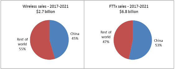
Sales of FTTx and wireless infrastructure optics will total almost $10 billion over the next 5 years.

The combined FTTx and mobile fronthaul and backhaul markets will consume more than 115 million optical devices in 2016, worth some $1.7 billion in revenue to components makers. Close to 70% of these products will be deployed in China. However, demand for access optics in China is projected to moderate in 2017-2021, since FTTH and 4G LTE upgrades are nearing completion. Access infrastructure projects in developing countries and deployments of next generation optics in the developed world, including China, are projected to sustain market growth in 2017 and beyond.

Global sales of optics for mobile infrastructure and FTTx are projected to exceed $2 billion by 2021 with the contribution of China declining to 50%. Despite modest growth forecasted for this market segment, it will remain a significant opportunity for suppliers, adding up to nearly $10 billion over the next 5 years, as illustrated in the figure below.

sales-of-fttx-and-wireless-infrastructure-optics
Figure 1: China as a percent of worldwide sales of access optics, 2017-2021

Chinese service providers will continue to invest in networking infrastructure, but their priorities are shifting from deployments of FTTH and wireless fronthaul optics to adding bandwidth in metro-access and metro-core networks. While China became number one in the world in terms of the number of FTTH and 4G LTE subscribers, the actual speed of Internet access in China remains below the global average. Lack of bandwidth in metro networks is considered a bottleneck and the government is urging service providers to resolve this problem.
Read more

The rules should be followed for cable plant hardware.

Various enclosures, cabinets, racks and panels are used to protect and organise splice and termination points. The network designer should know the type of network, support systems and the routes to be taken. Then the connection/splice locations can be determined and the hardware planned.

There are lots of rules to follow, of course (the EIA/TIA 569 has something to say about all this).

Here are some examples of fiber optic hardware:

  • Breakout kits – allow you to separate and protect individual fibres in a loose tube cable so it can be terminated
  • Splice enclosures – for long cable runs outside, the point where cables are spliced, sealed up and buried in the ground, put in a vault of some kind or hung off a pole
  • Splice panels – connect individual fibres from cables to pigtails
  • Patch panels – provides a centralised location for patching fibers, testing, monitoring and restoring cables
  • Racks and cabinets – enclosures for patch panels and splice panels. Usually these also include cable management – without this the cables start looking like spaghetti!

Demand for optics in China and Cloud datacenters will sustain the market growth in 2017-2021

demand-for-optics-in-china

It is hard not to get carried away with excitement about the optics market in 2016. Demand is at an all time high. Strong growth in sales of 100G DWDM and 100GbE products made a lot of headlines this year and expectations for 2017 are high. However, analysis of the broader market for optical components and modules uncovers a few problems. Apart from DWDM and Ethernet optics, all other market segments are likely to remain flat or decline in 2016. This includes SONET/SDH, Fibre Channel, FTTx, wireless fronthaul and optical interconnects (AOCs and EOMs).

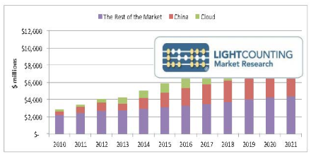
The total market for optical components and modules is expected to grow by 17% in 2016, with sales of DWDM and Ethernet products increasing by more than 30%. Massive deployments of 100G DWDM networks in China and 40GbE/100GbE optics in mega-datacenters by cloud-based companies are the main drivers of market growth this year and beyond, as illustrated in the figure below.

The total market for optical components and modules used in optical communications will grow at a CAGR of 10% in 2017-2021. Sales of optics to the cloud datacenter market will continue to grow rapidly in 2017-2021, averaging 20% annually.

The increasing contribution of China to the global market was related to its massive deployments of FTTx and wireless fronthaul optics in 2011-2015, but the situation has changed in 2016. This year it is demand for 100G DWDM and 100GbE optics that increased China’s share of the global market, and we think this trend will continue in 2017-2021.

The Market Forecast report provides a detailed market demand forecast through 2021 for optical components and modules used in Ethernet, Fibre Channel, SONET/SDH, CWDM/DWDM, wireless infrastructure, FTTx, and high-performance computing (HPC) applications. Key inputs include an analysis of the business and infrastructure spending of the top 15 service providers and leading Internet companies, and sales data from 2010 to 2016 for more than 30 transceiver vendors, including more than 20 vendors that shared their confidential sales information.

The rules should be remembered when you pulling fiber optic cable.

Installation methods for both wire cables and optical fiber cables are similar. fiber cable can be pulled with much greater force than copper wire if you pull it correctly. Just remember these rules:

1. Do not pull on the fibers, pull on the strength members only! The cable manufacturer gives you the perfect solution to pulling the cables, they install special strength members, usually duPont Kevlar aramid yarn or a fiberglass rod to pull on. Use it! Any other method may put stress on the fibers and harm them. Most cables cannot be pulled by the jacket. Do not pull on the jacket unless it is specifically approved by the cable manufacturers and you use an approved cable grip.

2. Do not exceed the maximum pulling load rating. On long runs, use proper lubricants and make sure they are compatible with the cable jacket. On really long runs, pull from the middle out to both ends. If possible, use an automated puller with tension control or at least a breakaway pulling eye.

3. Do not exceed the cable bend radius. fiber is stronger than steel when you pull it straight, but it breaks easily when bent too tightly. These will harm the fibers, maybe immediately, maybe not for a few years, but you will harm them and the cable must be removed and thrown away!

4. Do not twist the cable. Putting a twist in the cable can stress the fibers too. Always roll the cable off the spool instead of spinning it off the spool end. This will put a twist in the cable for every turn on the spool! If you are laying cable out for a long pull, use a “figure 8” on the ground to prevent twisting (the figure 8 puts a half twist in on one side of the 8 and takes it out on the other, preventing twists.) And always use a swivel pulling eye because pulling tension will cause twisting forces on the cable.

5. Check the length. Make sure the cable is long enough for the run. It’s not easy or cheap to splice fiber and it needs special protection. Try to make it in one pull, possible up to about 2-3 miles.

6. Conduit and Innerduct: Outside plant cables are either installed in conduit or innerduct or direct buried, depending on the cable type. Building cables can be installed directly, but you might consider putting them inside plenum-rated innerduct. This innerduct is bright orange and will provide a good way to identify fiber optic cable and protect it from damage, generally a result of someone cutting it by mistake! The innerduct can speed installation and maybe even cut costs. It can be installed quickly by unskilled labour, then the fiber cable can be pulled through in seconds. You can even get the innerduct with pulling tape already installed.

How to choose a right cable.

With so much choice in cables, it is hard to find the right one.

The table below summarises the choices, applications and advantages of each.

It will be helpful for you to choose a right one.

Cable type Application Advantages
Tight Buffer Premises Makes rugged patchcords
Distribution Premises Small size for lots of fibres, inexpensive
Breakout Premises Rugged, easy to terminate, no hardware needed
Loose Tube Outside Plant Rugged, gel or dry water-blocking
Armoured Outside Plant Prevents rodent damage
Ribbon Outside Plant Highest fibre count for small size

100GbE Optics is Starting to Light Up Cloud Data Centers, Setting Up Very High Expectations for 2017

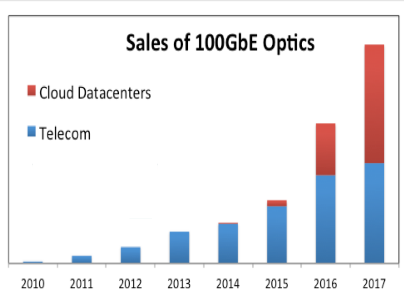
Volume deployments of 100GbE optics in mega data centers have finally started. The second half of 2016 is expected to be strong and 2017 should be even better. Demand is high and suppliers are scrambling to keep up. Shortages of high-end optics, such as EML and DFB laser chips, is the main limiting factor for 100GbE market growth in 2016.

The demand for 100GbE in telecom is also very strong, as illustrated in the figure below. Shipments of CFP and CFP2 transceivers were ramping up for several years and large telecom customers, led by Huawei, have a tight grip on the 100GbE supply chain. Sales of 100GbE for telecom applications will continue to increase, but Cloud Datacenters are expected to become the largest consumer of 100GbE optics in 2017.

100gbe-optics
The main surprise of 2016 so far is a very high demand for 40GbE datacenter optics. Leading cloud companies reduced purchases of 40GbE transceivers in late 2015 and that trend was expected to continue this year. Sales data collected by LightCounting for the first half of 2016, released in the latest quarterly market update report, showed very strong sales of 40GbE products.

Supply shortages in 100GbE optics contribute to the continuing deployments of 40GbE in mega data centers. The success of 40GbE, which has been looked down on as an intermediate step from 10GbE to 100GbE, clearly illustrates the need for just such intermediate steps. History is likely to repeat itself with adoption of 400GbE, benefiting 200GbE optics, which many consider an unnecessary step along the way. LightCounting’s latest Ethernet forecast, released with the High-speed Datacenter Optical Interconnects report, increases our projections for 200GbE products in 2018-2021.

The updated report leverages extensive historical data on shipments of Ethernet and Fibre Channel interface modules combined with market analyst research to make projections for sales of these products in 2016-2021. The report offers a comprehensive forecast for more than 50 product categories, including 10GbE, 25GbE, 40GbE, 50GbE, 100GbE, 200GbE, and 400GbE transceivers, sorted by reach and form factors. It provides a summary of the technical challenges faced by 100GbE transceiver suppliers, including a review of the latest products and technologies introduced by leading suppliers. The report is based on confidential sales information and detailed analysis of publicly available data released by leading component and equipment manufacturers along with considerable input from industry experts, including many mega datacenter operators.

Do you really need different cable testing devices?

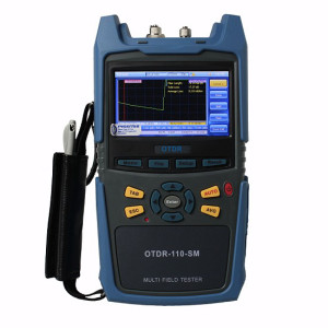
OTDRIt’s easy to be streaming a demo video in the middle of a teleconference with an important customer and NOT think about how this is actually happening. But if you are at all involved in structured cabling or network management, or share responsibility for these things from a facilities perspective, then you DO think about it. You know, for instance, that in recent years Ethernet speeds and bandwidth have increased by yet another order of magnitude. You also know higher speeds are the result of technological refinements that increase various interactions in the physical and data layers of a cable link over shorter periods of time in the same amount of space.

This complex interweave of materials, signal and math is the primary reason devices for testing LAN links have become so sophisticated. The sophistication comes in many forms—type and number of tests, speed, ergonomics, full color touch screen, document-based reporting—and causes devices to fall into a few basic categories. This is important because the cost associated with testing devices varies considerably with their purpose and their capabilities. This in turn suggests an overall strategy for cabling contractors to deploy multiple devices and helps both contractors and facilities managers avoid over- or under-spending in this area. More on that in a moment.

Cable and Network Testing

Let’s take a quick look at the breakdown of testing and devices. One of the simplest cable tests, called wire mapping, sends a signal down the link to see if anything is wrong, broken or missing.

A method called time domain reflectometry measures the speed of the signal and maps the channel topology, precisely locating any of a number of possible faults. Sometimes called OTDR or verifiers, these simple wire mapping devices are the equivalent of a pocket knife and should be hanging from every technician’s belt.

A somewhat more useful foundational cable testing device will be able to detect Power over Ethernet (PoE) and capture any networked phones, cameras or other low-voltage devices in the wire map.

The next step up in verifiers enables the technician to troubleshoot the network by identifying specific faults in both the physical and link layers in a channel. What does this mean? Simply that, in addition to broken or split wires, bad connections or other issues associated with the signal itself, the tester will perform a network discovery that tests the data protocols at each link to make sure all devices on the network are properly identifying one another.

Whether you are installing a new run or troubleshooting a faulty one, someone is going to need to test both the physical and link layers and prove that the network is operating to specifications. That takes us to a considerably higher level of testing, typically called qualification or transmission testing. But before we go there, let’s skip to the top for a moment.
Cable Systems and Network Certification

New builds and component manufacturer warranties typically require cabled systems to be certified. Certification means a pass/fail judgment of network performance based on a battery of tests performed, recorded and reported within a very specific procedural framework set forth by applicable TIA and ISO/IEC standards. This goes beyond the ability to determine whether your network does what you and your customer want it to do. You are proving, guaranteeing, certifying to the rest of the world that your network meets the same standards applied to every other network of that type or class. Moreover, it is not you that is doing the certifying, but rather your sophisticated, impartial, and, yes, expensive testing device. And there it is: the certifying tester itself is a product of global telecommunications standards. To be useful, it must be able to measure specifications well beyond those standards in order to render results within comfortable margins and provide headroom for the future. That’s why, for example, the WireXpert certifier from Softing was designed years ago with a frequency range up to 2,500 MHz—far in excess of the Category 8 cabling standard, which has only just now been approved.
Network Link Qualification

As a practical matter, certification only happens after everything has already been installed, fixed and tested. That leaves a lot of situations short of certification where the testing and reporting capabilities of a certifier could come in handy. That is the space occupied by qualifiers.

Softing’s qualifier, called NetXpert, leans toward the same lab-grade testing technology in a battery-powered handheld device that engineers developed for the WireXpert. Basically, the NetXpert qualifier does all the troubleshooting of cable/network testers with one very important addition: It can verify Gigabit Ethernet operation compliant with the IEEE 802.3ab standard. It does this through bit error rate test (BERT), a form of data transmission testing that sends 10 million bits in 10 seconds (1 Gbit/sec), counts the errors, then issues a PASS/FAIL. While distinct from certification, a BERT pass essentially proves the speed of a cable channel is up to standard.

In this way, LAN links are qualified as part of the installation, troubleshooting and repair procedure. You could think of a qualification pass as a sort of precertification that means whatever you are testing is working up to standards and you can move on. At less than a third of the cost of certifiers, it makes sense for every cabling crew to pack a network qualifier. On the other hand, at about twice the cost of a cable verifier it’s overkill to have everyone using them for routine wire mapping and troubleshooting.
Deploying Testing Devices

One way to understand the hierarchy among testing devices is to consider their deployment. Every cabling contractor location should have at least one certifier under a service contract plus one backup. Every crew needs to have a qualifier available to test the fix. Every technician should be carrying a cable verifier, whether they are part of a cabling contractor crew or a facilities management team.

Typically, cabling contractors will install, repair LANs for organizations even where there is an extensive facilities maintenance presence. But considering the high-performance nature of 10G+ Ethernet, it makes sense for in-house staff to be equipped to perform at least some of the initial wire mapping and troubleshooting activities. Where appropriate, cabling contractors should consider putting foundational tools like cable and network verifiers in their customers’ hands as part of a job or service agreement. It’s a good way to help customers retain control, save money and experience less network problem time. It also makes the contractor’s time and resources on service calls more efficient while giving their customers one less reason to do business with a competitor.

In addition to the WireXpert CAT-8 certifier and the NetXpert qualifier, Softing now offers the CableMaster line of cable and network verifiers to the North American market. (The CableMaster 800 is pictured above.) Don’t overspend and under deploy. Make sure you’re using the right testing device for the right job and that everyone on your team—including your customers—has what they need, when they need it.

What’s the cable design criteria ?

When you design the cable, you should know the following criteria.

1. Pulling strength

Some cable is simply laid into cable trays or ditches, so pull strength is not too important. But other cable may be pulled thorough 2 km or more of conduit. Even with lots of cable lubricant, pulling tension can be high. Most cables get their strength from an aramid fiber (Kevlar is the duPont trade name), a unique polymer fiber that is very strong but does not stretch – so pulling on it will not stress the other components in the cable. The simplest simplex cable has a pull strength of 100-200 pounds, while outside plant cable may have a specification of over 800 pounds.

2.Water protection

Outdoors, every cable must be protected from water or moisture. It starts with a moisture resistant jacket, usually PE (polyethylene), and a filling of water-blocking material. The usual way is to flood the cable with a water-blocking gel. It’s effective but messy – requiring a gel remover (use the commercial stuff – it’s best- -but bottled lemon juice works in a pinch!). A newer alternative is dry water blocking using a miracle powder – the stuff developed to absorb moisture in disposable diapers. Check with your cable supplier to see if they offer it.

3. Fire code ratings

Every cable installed indoors must meet fire codes. That means the jacket must be rated for fire resistance, with ratings for general use, riser (a vertical cable feeds flames more than horizontal) and plenum (for installation in air-handling areas. Most indoor cables us PVC (polyvinyl chloride) jacketing for fire retardance. In the United States, all premises cables must carry identification and flammability ratings per the NEC (National Electrical Code) paragraph 770. These ratings are:

NEC Rating Description
OFN Optical fiber Non-conductive
OFC Optical fiber Conductive
OFNG or OFCG General purpose
OFNR or OFCR Riser rated cable for vertical runs
OFNP or OFCP Plenum rated cables for use in air-handling plenums
OFN-LS Low smoke density

Cables without markings should never be installed as they will not pass inspections! Outdoor cables are not fire-rated and can only be used up to 50 feet indoors. If you need to bring an outdoor cable indoors, consider a double-jacketed cable with PE jacket over a PVC UL-rated indoor jacket. Simply remove the outdoor jacket when you come indoors and you will not have to terminate at the entry point. You can use an Indoor/Outdoor rated product with a Low Smoke Zero Halogen jacket.

Hyperscale data center market to reach $71.2 billion globally by 2022

According to a new market research report, the world hyperscale data center market is expected to reach a revenue of $71.2 billion by 2022, with a CAGR of 20.7% from 2016 to 2022.

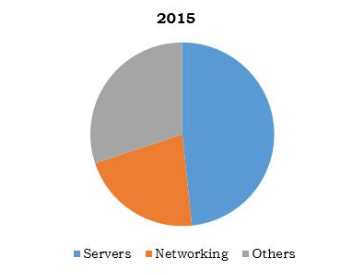
Global Hyperscale Data Center MarketGlobal Hyperscale Data Center Market, by Component, 2015 (% COMPARIOSN)

According to a new market research report, the world hyperscale data center market is expected to reach a revenue of $71.2 billion by 2022, with a CAGR of 20.7% from 2016 to 2022.

As stated by the analyst, “Hyperscale data centers are most widely adopted by cloud service providers to house cloud-based resources and cloud services, accounting for a market share of around 63% in 2015. North America is the largest revenue-generating region for hyperscale data centers, followed by Europe and Asia-Pacific in 2015.”

Key findings of the study include the following:

— The cloud provider segment was the highest revenue-generating segment, constituting over 63% of the total market revenue in 2015. The segment is expected to remain dominant throughout the analysis period.

— The enterprises segment is expected to generate a notable revenue of $7,095.2 million by 2022 growing at a CAGR of 27.7% during the forecast period.

— The rising demand for higher energy efficiency and increasing big data content are expected to drive the developments and advancements in the hyperscale data center market.

— Banking, financial services and insurance (BFSI) is likely to be the highest revenue-generating segment by 2019.

— Increased adoption of hyperscale data centers is anticipated to be witnessed across key sectors such as healthcare, manufacturing, and government utilities from 2016 to 2022.

— In 2015, North America was the highest revenue-generating region, constituting nearly 37% of the total market revenue.

Leading companies profiled in the report include Intel Corporation, Nlyte Software, Sandisk Corporation, Avago Technologies, Cisco Systems Inc., Hewlett-Packard, Ericsson, Cavium Inc., IBM, and Mellanox Technologies, Inc.