Archive for Fiber Optic Test Equipment

What factors affect optical fiber splicing loss?

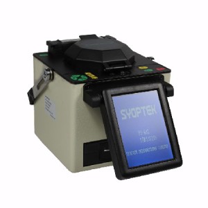
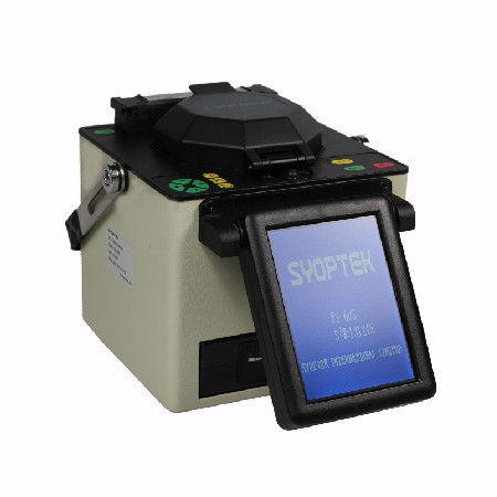
FS-60S Fusion SplicerThere are two types of factors that fiber splice loss depends on: intrinsic factors and extrinsic factors.
1、intrinsic factors
Mode Field Diameter Mismatch

Intrinsic factors are parameters that you can not control. These factors are determined when the fiber is manufactured and Mode Field Diameter (MFD) is the most critical one.

Differences in the mode field diameter between single mode fibers lead to a signal loss. More splice loss can be observed for higher difference in MFD values.
Read more

How to choose a best fiber optic power meter.

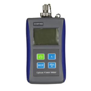
optical power meterFiber optic power meter measures how much light is coming out of a fiber optic cable; it can be used to determine the amount of light being generated by an optical source, or the amount of light being coupled into an optical receiver.

Optical power is usually measured in dBm, or decibels referenced to 1mW. These devices measure the average optical power, no the peak power, so they are sensitive to the duty cycle of the data transmitted. Their wavelength and power range have to be appropriately matched to the system being measured.

Most power meters used to best communication networks are designed to work at 850nm, 1300nm, and 1550nm wavelength ranges and in the power range of –15dBm to –35dBm for multimode links, or 0-40 dBm for single mode links.
Read more

How To Make A Perfect Fusion Splice?

fusion splicer

Fusion splice process is to literally weld two prepared fiber ends together, thereby creating a permanent joint with the minimum possible insertion loss. The fusion splice process is illustrated as follows.

Fusion Splice

So what factors in the fusion splice process determine the insertion loss achieved? The loss mechanism in fusion splice joint may be summarized as follows:

  • Core misalignment. Although normally aligned using the cladding diameter as the reference surface, it is generally believed that the complex surface tension and viscosity structures within the core and the cladding do tend to minimize the actual core misalignment.
  • Core diameter. The allowable diameter tolerances creates the possibility of attenuation within the joint.
    However, where differences between core diameters are large the welding of core to cladding inevitably takes place, which can either exaggerate or reduce the resultant losses. As a logical extension to this it should be obvious that optical fibers having different geometries are difficult if not impossible to joint using the fusion splice method.
  • Numerical aperture. The above comments regarding core diameter apply also to numerical aperture mismatches.

In addition to these losses, which are almost unavoidable, the level of skill involved in the process demands few abilities other than those necessary to prepare the fiber ends by cleaving. Nevertheless, poor levels of cleanliness and unacceptable cleaving of the ends will incur additional losses due to the inclusion of air bubbles or cracks. Incorrect equipment settings will also influence losses achieved and may result in incomplete fusion.

Fusion splicing is capable of producing the lowest loss joints within any optical fiber system, but their permanence limits their application. The need for demountable connections necessary to facilitate patching, repair and connection to terminal equipment forces the use of jointing techniques which use mechanical splices.

SYOPTEK's Quality and Reliable Fiber Optic Test Equipment

SYOPTEK designs and manufactures fiber optic test equipment for optical fiber cabling installing, maintenance, and verification; provides you quality, reliable fiber optic test equipment at a affordable price.

SYOPTEK fiber optic test equipment line includes Fiber Optic Inspection Probe, Fiber Optic Inspection Microscope, Optical Light Source, Optical Power Meter, Optical Fiber Identifier, Fusion Splicer, and Visual Fault Locator.


Optical network trends for 2013

These overarching themes will keep evolving in 2013. As the world becomes increasingly connected and mobile, all of the tech companies that touch the network are pushed to find new ways to remain relevant to survive. They must continue honing their business models and operations for maximum efficiency in an unpredictable economic environment. They must continue building out faster and more flexible networks to support increasing and more random traffic patterns. And they must continue to create innovative products and services that support our need for instant access via new apps and the next shiny and new connected device that captivates us based on increasingly shorter product cycles.

This is not breaking news, but themes that will intensify throughout 2013. Here’s a look at how these themes will play out in various aspects of optical networking. Read more

2014 Annual Technology Forecast

From a technology perspective, silicon photonics became a bogeyman for some and a fairy godmother for others, depending on whether you were working on the technology or not. Software-defined networking (SDN) vied with silicon photonics for “Buzzword of the Year,” while network functions virtualization (NFV) tagged along for the ride. And all the noise made last year about colorless/directionless/contentionless ROADMs died down.
The deployment of 100-Gbps technology kicked into high gear – except in the data center, where 40 Gbps is just getting established. Nevertheless, the IEEE determined that it’s not too early to begin thinking about what comes next and decided it’s 400 Gigabit Ethernet. In carrier networks, a small handful of companies offered 400 Gbps, but carriers started to talk about breaking that in half and deploying 200 Gbps. Read more

Fiber Optic Fusion Splicers and How They Work

What is a fiber optic fusion splicer?

A fiber optic fusion splicer is a device that uses an electric arc to melt two optical fibers together at their end faces, to form a single long fiber. The resulting joint, or fusion splice, permanently joins the two glass fibers end to end, so that optical light signals can pass from one fiber into the other with very little loss.

How does a fusion splicer work?

Before optical fibers can be successfully fusion-spliced, they need to be carefully stripped of their outer jackets and polymer coating, thoroughly cleaned, and then precisely cleaved to form smooth, perpendicular end faces. Once all of this has been completed, each fiber is placed into a holder in the splicer’s enclosure. From this point on, the fiber optic fusion splicer takes over the rest of the process, which involves 3 steps:


  • Alignment: Using small, precise motors, the fusion splicer makes minute adjustments to the fibers’ positions until they’re properly aligned, so the finished splice will be as seamless and attenuation-free as possible. During the alignment process, the fiber optic technician is able to view the fiber alignment, thanks to magnification by optical power meter, video camera, or viewing scope.


  • Impurity Burn-Off: Since the slightest trace of dust or other impurities can wreak havoc on a splice’s ability to transmit optical signals, you can never be too clean when it comes to fusion splicing. Even though fibers are hand-cleaned before being inserted into the splicing device, many fusion splicers incorporate an extra precautionary cleaning step into the process: prior to fusing, they generate a small spark between the fiber ends to burn off any remaining dust or moisture.


  • Fusion: After fibers have been properly positioned and any remaining moisture and dust have been burned off, it’s time to fuse the fibers ends together to form a permanent splice. The splicer emits a second, larger spark that melts the optical fiber end faces without causing the fibers’ cladding and molten glass core to run together (keeping the cladding and core separate is vital for a good splice – it minimizes optical loss). The melted fiber tips are then joined together, forming the final fusion splice. Estimated splice-loss tests are then performed, with most fiber fusion splices showing a typical optical loss of 0.1 dB or less.

SYOPTEK brings the fiber optics industry a new and exciting choice in high quality, dependable, and full-featured fusion splicer and test equipment.