Archive for Learning Center

One-Click Cleaner

The One-Click Cleaner is an easy-to-use option for cleaning connectors in adapters. Simply insert the One-Click Cleaner into an adapter and push until an audible “click” is heard. The One-Click Cleaner uses the mechanical push action to advance an optical grade cleaning tape while the cleaning tip is rotated to ensure the fiber end-face is effectively, but gently, cleaned.

The One-Click Cleaner is a must-have for field technicians. Small enough to fit in a shirt pocket and a great addition to cleaning kits.

Save your wrist – no more twist!

Features:
• Ergonomic, comfortable design with single action cleaning
• Precise mechanical action delivers consistent cleaning results
• Effective on a variety of contaminates including dust and oils
• Automatically advance ensures each clean is performed with fresh cleaning tape
• Low cost per clean
• Compliant with EU/95/2002/EC Directive (RoHS)

Applications:
• Cleans connectors on jumpers and in adapters
• Cleans a wide variety on connector types

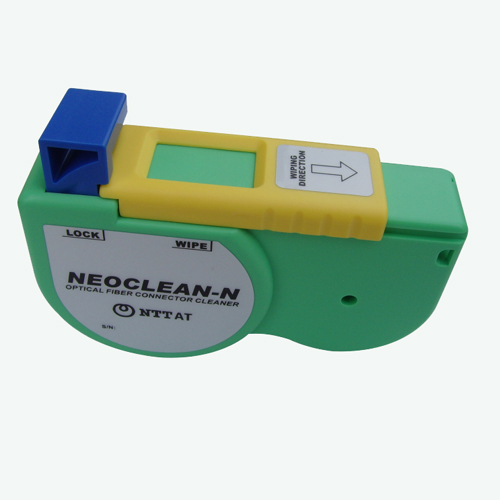
NEOCLEAN-N Optical Connector Cleaner

The NEOCLEAN-N is a simplified and a replaceable reel type cleaner for ferrule end-faces. It enables low cost cleaning.


Features:
– Cassette case made with anti-static resin
– An alcohol-free dry cloth solution
– Palm-sized and lightweight
– Efficient and easy to use
– Delivers consistently high quality cleaning performance
– Specially washed, high-densely woven, micro-fiber cleaning tape
– Each cassette provides approx. 400 ferrule cleaning cycles

Specifications:

Product name

NEOCLEAN-N

Part No.

ATC-NE-N

Connectors cleaned

SC,FC,ST,MU,LC,MPO,MT,MT-RJ(w/o pins)

Dimension

L115mm × W25mm × H55mm

Cleaning Cycle

One cassette provides more than 400 ferrule cleaning cycles

TE Connectivity, Fiber-Span collaborate on public safety DAS

TE Connectivity  has announced a new public safety distributed antenna system (DAS). Developed in collaboration with Fiber-Span, the code-compliant DAS platform supports primary public safety and critical first responder frequencies in the VHF/UHF/700/800/900/TETRA frequency bands on a single system.

The new DAS is designed to provide high-reliability coverage NEOCLEAN for public safety communications services for both in-building and outdoor applications.
“We are excited to extend our partnership with Fiber-Span,” fiber optic cleaning kit comments Peter Wraight, president of TE’s Wireless business unit. “With collaboration from Fiber-Span. “TE developed this solution to ensure life safety protection for the public as well as police, firefighters and other first responders.”

TE will showcase the new public safety DAS platform at the “DAS & Small Cells Congress” in Las Vegas, fiber optic microscope NV on June 17-18, 2014, in booth 301. Ideal 45-163 The solution will be available by Fall 2014, fiber optic tools says the company.

Fiber Optic Power Meter

Once you install and terminate fiber optic cables, it’s time to test them. A test should be conducted for each fiber optic cable plant for three main areas: continuity, loss, and power. To do this, you’ll need a optical power meter. Here’s a quick guide to fiber optic power meters and how they work.

Before Using a Power Meter

There are a few things you should do to prepare before using a fiber optic power meter. First, read the manual and run some practice tests with your power meter before going onto the job site. Next, prepare documents showing how and where all your cables are installed. Don’t depend on memory because you can easily lose track of your cables, especially if it’s a large project. Also, create a worksheet to document your testing data. Some power meters have a memory feature for keeping your data. These come in handy for large projects as well.

Use Safety Precautions

It’s important to follow safety precautions while testing fiber optic cables with a optical power meter. Wear eye protection when working with high-power cables. Even with low-power layouts, it’s wise to check the connectors with your power meter before looking.

Using a Power Meter for Power Measurement

When measuring fiber optic power with a power meter, attach the meter to the cable. Turn on the source of power (transmitter), and view the meter’s measurement. Compare the meter measurement with the specified correct power for that particular system to be sure it doesn’t have too much or too little power. The reason correct power measurement is so important with fiber optic cables is because the system works similar to electric circuit voltage, and the power must be just the right amount to work properly.

Testing Loss with a Power Meter

A power meter is used to test loss, but a test source is needed as well. The meter will measure the optical power that is lost in every part of the cable. The cable is mated with a working reference cable. Two methods used in loss testing are single-ended loss and double-ended loss. With single-ended loss testing, only the launch cable is used. With double-ended loss testing, a receive cable is also attached to the meter.

There are certain loss guidelines to follow for connectors, splices, multimode fibers, and singlemode fibers. You should understand these guidelines as well as the standard formula for calculating loss before getting started. Many training tutorial sites online provide these guidelines free of charge.

Other tools that may be required for the processes above include optical loss test kits, matching reference test cables, mating adapters with hybrids, a visual fault locator or fiber tracer, fiber optic cleaning items, and an ODTR (for outdoor networks).

Fiber optic cables can be of great value to companies if they work properly. Use a fiber optic power meter and other useful tools to ensure that your fiber optic system will operate smoothly around the clock.

Fiberopticcleanings.com stocks a variety of fiber optic cleaning supplies, from one click cleaners to NEOCLEAN-N optical connetor cleaner, from fiber optic cleaning wipes to fiber optic cleaning kit – everything you need for fiber optic cleaning jobs, BUY NOW and get FREE SHIPPING on most items!

Zhone, Fujitsu partner to install FTTH networks in rural New Mexico

Fiber-to-the-x (FTTx) systems supplier Zhone Technologies (NASDAQ: ZHNE) has partnered with Fujitsu Network Communications, Inc., in the development of a fiber-to-the-home (FTTH) network for Kit Carson Electric Cooperative (KCEC), which will enable gigabit broadband services for rural counties in Northern New Mexico.

Fujitsu worked with KCEC to select Zhone for its ability to meet the standards required in the FCC’s National Broadband Plan: delivering affordable high-speed broadband service in excess of 100 Mbps to residents and 1-Gbps broadband service to anchor institutions like schools, hospitals, and government offices.

“As the network systems integrator, we’re thrilled to have Zhone provide the last mile access solution that will give Kit Carson Electric Cooperative’s members and broadband providers a reliable, fiber optic cleaning kit resilient and high-speed fiber network with the required bandwidth to satisfy their needs,” said Greg Manganello, senior vice president and head of services, Fujitsu Network Communications. “Zhone’s FTTH products were selected because they met this project’s selection criteria for future-proofing, security, interoperability and management.”
 
Spanning 2,400 miles along KCEC’s existing electric distribution right-of-way, the fiber-optic network will connect 29 communities comprised of roughly 24,000 households and businesses, 183 critical community institutions, and two Native American pueblos within a 2,951 square mile underserved area in the Taos, Colfax, and Rio Arriba counties in Northern New Mexico. fiber optic tools The entire area will be serviced with a new network that will be built out in four phases, taking about two years to complete.

In addition to video, voice, and data services for consumers and anchor institutions, the fiber-optic network will also enable “smart grid” technologies for the utility operator, including substation automation (SA) and advanced metering infrastructure (AMI) technology.

Based on GPON technology, fiber optic tool kit the network will be powered by Zhone’s MXK access platform and zNID optical network terminals (ONTs). The company will also construct a secure network facility within its existing corporate headquarters. The first phase will include four sites with four MXKs and 1,500 zNID-GPON-4220 set to reach 5,900 homes, with a goal of reaching 19,000 homes when the project is complete.

C Spire launches 1-Gbps FTTH network construction

C Spire said May 8 that it has launched construction of a planned statewide fiber-optic network that would support 1-Gbps fiber to the home (FTTH) connections in Mississippi. The service provider asserts the network will be the first in the U.S. to provide 1-Gbps FTTH services across an entire state.

The company held a press conference to mark the laying of fiber-optic cable in the Bridgewater neighborhood of Ridgeland, one of nine communities on which C Spire will focus its efforts initially. Other communities include Batesville, Clinton, Corinth, Hattiesburg, Horn Lake, McComb, Quitman, and Starkville. In addition to the activities in Bridgewater, C Spire says it also has begun infrastructure deployment in Quitman and will soon begin work in Horn Lake and Starkville.

C Spire announced the effort last fall. Borrowing a page from Google, it issued an RFI to communities in the state who might want to receive 1 Gbps FTTH service. While C Spire originally planned to select a single community from among the RFI respondents, it expanded its initial target to the nine communities in light of the significant interest shown .

Again mimicking Google, C Spire then encouraged citizens in each of the nine communities’ neighborhoods to sign up for service, with those neighborhoods reaching a predetermined target percentage of registrants receiving service first.  C Spire reports that all of the “fiberhoods” in Quitman reached their quotas. In all, four of the cities have seen enough pre-register to qualify six areas for FTTH deployments, C Spire says, with the expectation that other neighborhoods would reach qualification levels soon. Pre-registration is expected to remain open through the end of this year.

The new network is expected to improve quality of life, boost business activities, and increase jobs throughout the state. “Fiber to the Home is a transformative technology for communities, serving as a platform for innovation and new Internet experiences yet to be imagined,” said C Spire CEO Hu Meena at the press conference. “We’re going to show the world that Mississippi is ready to become a hub for technology investment, economic growth, and job creation.”

Added FTTH Council Americas President Heather Burnett Gold, who also attended the press conference, “Increasingly, communities and companies around the U.S. are recognizing the power that FTTH brings, and we’re glad to be celebrating in Mississippi, a state that has not traditionally led the digital charge, but where individuals, communities and technology companies like C Spire recognize that they must take control of their own broadband destinies to secure a high-tech future.”

C Spire says it expects to begin offering services on its new FTTH infrastructure this summer.

Inspection and Cleaning Procedures for Fiber-Optic Connections CISCO(4)

Cleaning Techniques for Bulkheads and Receptacles

Receptacles refer to packaged devices with optical ports. Many receptacle devices use lens based systems which are less sensitive to contamination as opposed to fiber, but can be damaged if cleaned improperly. If you inspect a receptacle device and are not able to focus on the endface cladding, then you have a lensed device and should not attempt to clean it. See Figure 14 and Figure 15 for sample images of the endface core and cladding.

Cisco has found that the use of swabs for cleaning is not always very effective even for experienced operators. It might be better to leave an optical port alone unless signal effecting contamination is observed blocking the core. Contaminants can be pushed onto the endface in the process of the insertion of the swab.

caution Caution: Wet cleaning is not recommended for bulkheads and receptacles. Damage to equipment can occur.

Always make sure you plug in a clean mating connector in order to avoid cross contaminating the receptacle side. Ground in contamination is much harder to remove than loose debris.

Remember, inspect first and clean only if necessary!

Dry Clean: Lint-Free Swabs

This section describes dry cleaning techniques that uses lint-free swabs.

Tools

  • Lint-free swabs

Figure 12

117074.gif

caution Caution: Never clean bulkheads or receptacles without a way to inspect them afterwards. Cleaning can actually leave the endface in a worse condition.

caution Caution: Read the reminders and warnings before you begin this process.

  1. Make sure that the lasers are turned off before you begin the inspection.

    warning Warning: Invisible laser radiation might be emitted from disconnected fibers or connectors. Do not stare into beams or view directly with optical instruments.

  2. Remove the protective endcap and store it in a small resealable container.

  3. Inspect the fiber connector in the adapter or bulkhead with a fiberscope probe. Refer to the Connector Inspection Technique section.

  4. If the adapter is dirty, select the appropriate lint-free swab according to the connector ferrule size.

  5. Inspect the connector in the adapter again with a fiberscope probe.

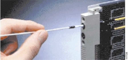
  6. Insert the clean lint-free swab into the adapter. See Figure 13.

    Figure 13

    117725.gif

  7. Turn the swab several complete revolutions in the same direction.

  8. Properly dispose of the swab. Never reuse a swab.

  9. Repeat the cleaning process as necessary.

Wet Clean: Lint-Free Swab

caution Caution: Improper cleaning can cause damage to equipment. The primary concern with the use of isopropyl alcohol is that it can be removed completely from the connector or adapter. Residual liquid alcohol acts as a transport mechanism for loose dirt on the endface. If the alcohol is allowed to evaporate slowly off the ferrule, it can leave residual material on the cladding and fiber core. This is extremely difficult to clean off without another wet cleaning and usually more difficult to remove than the original contaminant. Liquid alcohol can also remain in small crevices or cavities where it can re-emerge during fiber connection.

caution Caution: On female multifiber connectors, ensure no alcohol gets into the guide pin holes or it can come out during mating and contaminate your connection.

Tools

  • 99% isopropyl alcohol

  • Lint-free swabs

caution Caution: Never clean bulkheads or receptacles without a way to inspect them afterwards. Cleaning can actually leave the endface in a worse condition as alcohol residue is one of the most difficult contaminants to remove.

  1. Make sure that the lasers are turned off before you begin the inspection.

    warning Warning: Invisible laser radiation might be emitted from disconnected fibers or connectors. Do not stare into beams or view directly with optical instruments.

  2. Remove the protective endcap and store it in a small resealable container.

  3. Inspect the connector with a fiberscope. Refer to the Connector Inspection Technique section.

  4. If the dry cleaning procedure did not remove the dirt from the fiber endface, then place one drop of 99% alcohol to lightly moisten a new lint-free swab. Do not oversaturate the swab.

    Tip: Have a dry lint-free swab available for drying immediately after the cleaning. Make sure that the drying swab stays clean. See Caution

  5. Lightly press and turn the dampened swab to clean the ferrule face.

  6. Immediately after you clean, lightly press and turn the second swab (dry) to dry any alcohol that remains from the ferrule face.

  7. Properly dispose of the wet and dry swab. Never reuse a swab.

  8. Inspect the connector again.

Fiberopticcleanings.com stocks a variety of fiber optic cleaning supplies, from one click cleaners to NEOCLEAN-N optical connetor cleaner, from fiber optic cleaning wipes to fiber optic cleaning kit – everything you need for fiber optic cleaning jobs, BUY NOW and get FREE SHIPPING on most items!

Singlemode pre-angled MT ferrule eliminates polishing fixture, improves fiber connection

Fiber-optic connection specialist US Conec has unveiled singlemode pre-angled thermoplastic MT ferrules that it says will significantly improve the fiber connection process in terms of efficiency and performance. The pre-angled design eliminates a polishing fixture, which reduces polishing time during the production process and improves the MT ferrule’s performance, US Conec explains.

The ferrules are available in 12-fiber and 24-fiber variants. fiber optic tools They are compatible with MTP-brand MPO fiber-optic connector components and with IEC 61754-5 and IEC 61754-7 standards, the company adds.

In addition to the reduction in process time, elimination of the polishing step also benefits performance, US Conec says. The design enables better control over polished length, fiber optic cleaning kit which directly affects the connector spring force and MT ferrule performance, the company explains. The fact that less equipment is needed reduces capital costs as well, US Conec points out.

“Customers will immediately appreciate the reduction in process time,” neoclean comments Sharon Lutz, ferrules product manager at US Conec. “Traditionally, singlemode ferrules would be loaded into a flat polishing fixture for an epoxy removal step and then unloaded and reloaded into an angled polishing fixture. Pre-angled ferrules eliminate this step, reducing the operational complexity of the cable assembly maker.”

Converging network layers will expand service provider revenues

The challenge has been well known for a decade: Service providers are investing billions of dollars into infrastructure, but the resulting networks are complex and expensive to operate. To make matters more difficult, service provider business models are changing. Traffic is increasing rapidly over their more complex and powerful networks, but revenue remains relatively flat and untenable in the long run.

There is also a major transition in the services offered over these networks, from long-term circuit-based services with predictable bandwidth, to mostly best-effort, on-demand, interactive data services with rich quality-of-experience requirements.

Service providers have identified a number of shortcomings that make it difficult to respond to these evolving service requirements. They include:

  1. Rigid network structures that are not suitable for the unpredictable, fluctuating, and increasing traffic load.
  2. Long-term, static service provisioning that cannot rapidly meet agile on-demand customer requirements.
  3. Layers of special purpose equipment, which result in complicated and inefficient provisioning and management.

These network issues are being addressed by a number of industry organizations. For example, service providers have banded together to develop network functions virtualization (NFV) standards under the auspices of ETSI to better define problems and propose long-term solutions. The Open Networking Foundation (ONF) is another group with similar objectives. They are creating software-defined network  (SDN) specifications based on the OpenFlow protocol that abstract control from multiple layers and, in effect, collapse layers through software control.

As a result of these and other efforts, carriers and content providers are advocating a new paradigm for intelligent networks that collapses network layers and improves network efficiency.

The path toward convergence
The new paradigm’s advanced capabilities will be realized through:

  • virtualization
  • software programmability
  • layer convergence in network equipment
  • application awareness.

The NFV and SDN initiatives address the operational expense incurred by traditional large networks consisting of back-to-back devices, often in the same site, each with its own control plane and management software. Today, creation of an end-to-end service may require configuration of separate devices for Layer 3 routing, Layer 2 Ethernet, and Layer 1 optical. Configuration of, for example, BGP and IGRP at Layer 3, Carrier Ethernet bandwidth profiles, OAM and quality of service (QoS) at Layer 2, and Optical Transport Network (OTN) at Layer 1 — all using IPv4 and IPv6 — requires significant equipment, labor, and expense.

Meanwhile, service provisioning and delivery requirements have evolved. In the past, it might take 60 days to create a new service; now customers want it in 60 seconds. In addition, customers may change day-to-day requirements for more, less, or different services and they are willing to pay for this flexibility.

The solution is to build a network that is intelligent enough to make decisions about different layers using instantaneous traffic awareness and deliver SLA-compliant services based on traffic management, QoS, and security implementations from a single hardware and software platform. To support this requirement, collapsing some OSI layers into a single, more intelligent device should provide greater control, more efficient network design, faster service provisioning, and lower operational expenses.

The question is, what will converged equipment, a converged network, or converged management look like?

The look of the future
The investment in existing protocols – e.g., OTN, IP, IGP, BGP, EGP, MPLS, VPLS, MPLS-TP, VRF, PBB, PBB-TE, Carrier Ethernet 2.0. plus vendor proprietary protocols – is significant, and these protocols are difficult to orchestrate into a simple management system. Coordinating them across multiple autonomous networks will be an even larger challenge. Nevertheless, the diagram below shows how today’s Layer 1-3 protocols map into a new converged network.

Figure 1. The transition from today’s infrastructure to a converged network.

Proactive companies are adopting industry standards to enable layer convergence. We see this integration with the morphing of Layer 1 optical functions like mux/demux into switch routers, and conversely we see switching blades added to formerly pure WDM transport systems. Using low-latency optical/electrical/optical functions like cut-through switching and sophisticated packet processing that gives priority to individual flows will enable the efficient grooming of packets for transmission over wavelengths and preserve the low-latency characteristics of WDM transport. OTN may play a critical role in switch router equipment that integrates ROADM, forward-error correction (FEC), OTN, and other formerly optical transport characteristics.

The implementation of other protocols in these converged devices will further enhance the simple orchestration and control of dynamic, flexible new services. The IETF standard for path computation elements (PCEs) can play a role in provisioning and route restoration. Another IETF standard, ALTO, could serve as a resource mapping service for layer coordination. OpenFlow has a similar mission of creating an abstraction layer that enables graceful orchestration of heterogeneous network equipment.

Additional efforts are needed

These efforts, while impressive, are a long way from being the comprehensive solutions that the industry needs, however. To create a converged network, these protocols must encompass a vast number of functions and applications that include:

  • Performance optimization of network stacks on virtualized systems
  • Verification of unknown code running on shared platforms
  • Extensible software stacks for implementation of new functions
  • Mechanisms for migration of stateful devices
  • Resource allocation mechanisms for shared/virtualized platforms
  • Integrating new software into legacy networks
  • Management abstractions and policy language frameworks
  • Measurement of service performance in service provider networks
  • Security, performance, and monitoring applications
  • Challenges for policy verification of new service and devices.

New protocols and hypervisors with APIs, TLVs (type-length values), MIBS (management information bases), and new data models will be needed to create the basic tools to implement these functions. Standards organizations like the OIF, ONF, IETF, IEEE, ITU-T, and others will each provide pieces of the solution. Optical vendors will implement more software with these protocols along with proprietary functions for their transport platforms to create the foundation for new flexible services and more efficient modes of operation.

Converged networks will have awareness of the underlying traffic patterns and content to help optimize performance and insure QoS. One approach to this goal is s-Flow (see below), a protocol that samples flow data and analyzes content to help optimize network resources.

Figure 2. Protocols such as s-Flow likely will be needed to supplement the specifications
from organizations such as the NFV and ONF.

Networks will need to be aware of thousands of services in parallel, requiring efficient packet processing and hashing algorithms. Dedicated deep packet inspection (DPI) and analytics engines will become the distributed policy enforcement mechanisms of these new converged networks.

In the optical realm, auto-power balancing and BER will be routinely tracked for all links and transceiver pairs. These mechanisms will become part of a real-time, distributed, dynamic network capable of changing rapidly even as they support hundreds of thousands of flows.

These developments in network convergence promise significant long-term operational efficiencies for service providers. In the closed confines of the modern data center, we have seen some promising trends in convergence. Migrating these operational advantages to the wider service provider community will happen over the coming years as standards develop and newer devices with more powerful processing, open APIs, and integrated switching/routing/optical transport hardware come to market.

Due to the number and complexity of the protocols involved in wide area networking, a standards-based, evolutionary approach is preferable over a radical telecommunication overhaul from both a cost and performance perspective. Industry support for these new approaches to converged networks will create dynamic, fluid, and operationally efficient service provider operations.

Mannix O’Connor is director of technical marketing for MRV Communications. He can be reached atmoconnor@mrv.com
OTDR conducts bidirectional testing without moving unit from near end to far end

The SmartLoop OTDR is a new test instrument from Fluke Networks that the company says cuts fiber-test time in half because the test crew does not have the move the OTDR from one end of the fiber to the other in order to conduct bidirectional tests. “Bidirectional testing has traditionally been a length process,” the company said, “requiring traveling some distance to the far end of the fiber or taking equipment into hazardous or difficult-to-access areas. The SmartLoop OTDR is the industry’s first product to test two separate fiber links in a single test. Not only does this eliminate the need to travel to the far end of the connection to perform tests, it also cuts network testing time by 50 percent.”

According to Fluke Networks, the tester uses patent-pending algorithms to automatically separate fibers for individual pass/fail analysis and display, which further enhances the ease and speed of testing.

The graphic above was created by Fluke Networks and illustrates the differences in procedures and efforts between traditional OTDR testing (bottom) and testing with SmartLoop OTDR (top). The top image shows the inclusion of a loopback cable at the far end of the link. With that loopback cable in place, the test technician separately connects the OTDR to each of the fibers on the near end. Upon launch, the OTDR sends the test signal down one fiber, then down the other in the reverse direction, before reversing path and returning to the OTDR. Once the technician has done this for both near-end fibers, the testing is done. The bottom image details the multiple steps necessary for traditional OTDR testing—most notably, moving the OTDR to the far end in order to test “direction 2” for both fibers.

SmartLoop OTDR is an addition to Fluke Networks’ OptiFiber Pro OTDR and is available as a free update to owners of the Versiv platform.