Archive for Learning Center

AT&T moves forward with municipal gigabit FTTH plan in North Carolina

AT&T announced that city officials in Winston-Salem, N.C. have ratified an agreement that will clear the way for AT&T to offer the municipality its 1-Gbps U-verse with GigaPower service via fiber-to-the-home (FTTH) networking installations.

Winston-Salem is the first of six cities that are part of the North Carolina Next Generation Network (NCNGN) initiative to ratify an agreement for 1-Gbps FTTH with AT&T. As reported by CablingInstall.com’s sister site, Lightwave, the service provider announced an initial agreement with the NCNGN cities this past April. fiber optic cleaning kit The other five cities are Cary, Chapel Hill, Carrboro, Durham, and Raleigh. NEOCLEAN City leaders in each of these cities have similar agreements with AT&T under review. Four universities – Duke University, North Carolina State University, University of North Carolina at Chapel Hill, and Wake Forest University/Wake Forest Baptist Medical Center – are part of the NCNGN as well.

The group of municipalities and associated universities issued an RFP in February 2013 in search of a partner or partners to help build high-speed broadband access networks in the region. AT&T was one of eight respondents to the RFP, and in April of this year the NCNGN Steering Committee approved a resolution that its members seek authorization to enter master network development agreements with AT&T. The plan AT&T proposed to the NCNGN includes options for public Wi-Fi hotspots, free AT&T U-verse with GigaPower at up to 100 public sites, and an all-fiber-optic network connected to up to 100 business buildings. It also outlines a free 3-Mbps AT&T U-verse Internet offer that would be available to 10 affordable housing complexes, fiber optic microscope up to 3000 homes. The hotspots, public sites, buildings, and apartment complexes covered by this part of the proposal would cross the six communities and be identified by NCNGN.

AT&T did not say when the 1-Gbps services would become available in Winston-Salem. U-verse services with lower data rates are currently available in the city, as well as in all of the other NCNGN cities except Durham, home of Duke University. Ideal 45-163 In addition to the NCNGN cities, the carrier also hopes to extend the 1-Gbps GigaPower service to Greensboro and Charlotte, N.C., part of a recently released list of 21 markets that may see 1-Gbps FTTH offered by AT&T.

“We’re thrilled that Winston-Salem will be in the next round of cities for AT&T’s rollout of its U-verse with GigaPower,” commented Winston-Salem Mayor Allen Joines. ” fiber optic tools Our city has a well-deserved reputation as a technology and medical leader and a network of this magnitude will help take the work underway in both those areas to new levels of innovation and achievement.”

100G reaches the metro

Metro networks weren’t the first applications of 100-Gbps technology. But operators within the niche appear to be making up for lost time.

As 100-Gbps deployments in long-haul networks gained momentum last year, several observers thought a less expensive alternative would have to be offered for 100 Gbps to see widespread deployment in the metro, particularly for data-center interconnect.

Events this year have proven such fears unfounded. This year’s tide of 100-Gbps deployments includes several examples within metro/regional networks. But that doesn’t mean those who called for a different technical approach to the metro were wrong.

Pent up demand

The increasing number of metro/regional 100-Gbps deployments highlights how quickly bandwidth demand has grown across network niches.

“Metro 100 gig has ramped quite well for us. About half of our customers that are deploying 100 gig are deploying 100 gig in the metro,” says Michael Adams, vice president, product and technology marketing at Ciena Corp. The company counts CenturyLink and XO Communications among its high-profile metro 100G customers.

Systems that use coherent detection have proven almost as popular in metro applications as they have in the long haul. Photo courtesy of Ciena Corp.

Ciena has found a healthy demand for both direct 100 Gigabit Ethernet (100GbE) connections – mainly for router interconnect, particularly from the larger carriers – and 10×10-Gbps muxponding. “Right now I would say almost about 40% of our deployment is with 100GbE, in the context of running them over 100-gig waves,” Adams explains. “Now that’s skewed a little bit to a smaller number of customers. I would say from a number-of-customers perspective, the statistic would be more skewed to 10×10G.”

Mike Sabelhaus, who works on optical solutions for Fujitsu Network Communications, reports that 100G technology has appealed to several different carrier types. For example, one “large east coast wireless network operator” is using the technology to connect routers for mobile backhaul, he says. Wireless operators in general have adopted 100G for connecting mobile switching centers, Sabelhaus adds. Elsewhere, another large carrier customer has incorporated 100G technology into its network to meet a trio of requirements: fiber relief via 10G muxponding, IP router aggregation/interconnection, and support of Optical Transport Network (OTN) switching requirements.

Cable operators have interest in the technology as well. “A lot of what we’re seeing in the cable networks is using it for their metro transport networks, hub site to hub site within a city or region, and potentially to connect backbones together or other regions together,” Sabelhaus notes.

Like his competitors at Ciena, Sabelhaus sees significant interest in both direct 100GbE connections and muxponding applications. That trend should continue in the future, he says, based on his projections for demand between this year and 2015. “In the transponder area, I’m seeing roughly 50% to 75% growth from year to year,” Sabelhaus reveals. “And muxponder is in the 30% to 40% growth area.”

Demand for high-speed metro/regional pipes drives not only sales of 100G platforms, but also 100G network services. Zayo Group has just started to deploy its first customer-requested 100-Gbps metro link after building a metro-centered extension of its long-haul network for another customer.

The drivers for 100-Gbps network services are similar to those the systems vendors have encountered, reports Zach Nebergall, head of the wavelength product unit at Zayo. “Data center to data center is I’d say the primary driver we’ve seen so far,” Nebergall says. “In the carrier segment, I’d say there is a similar dynamic, but a PoP [point of presence] to PoP scenario; with the wireless guys, it’s a mobile switching center to PoP.”

Coherence around coherent

Another commonality among the majority of metro/regional deployments is use of coherent transmission technology. Part of this trend may be that only one optical hardware supplier – ADVA Optical Networking – has commercialized an alternative that uses direct detection (more on this later). Nevertheless, coherent has proven more attractive than the doubters had believed.

Helen Xenos, Ciena’s director of product and technology marketing, asserts that from a technical standpoint, coherent is popular for metro/regional applications for the same reasons it’s popular in long-haul networks. It works on just about any fiber, is spectrally efficient, and delivers robust performance in the face of impairments.

Comfort with the technology also has proven a major factor with some deployers. “Given that it’s early in the deployments, we think that the cost basis was still there, that we could make the same technology work,” Nebergall says of Zayo’s decision to use coherent technology. “The tradeoffs didn’t make sense to us such that we’d move off of a piece of equipment that we were pleased with so far.”

Yet, just because you’re using the same system in your metro/regional and long-haul networks doesn’t mean you’re using exactly the same technology. For example, Adams acknowledges that Ciena has a portfolio of coherent combinations for different applications. While declining to provide a great deal of detail, he reveals that Ciena supports more than one approach to forward error correction so customers can balance reach and latency requirements. “We’ve talked about in the past that for metro, as an example, one possibility going forward is using 16QAM tuning capability to have a 50% economic improvement in metro/regional 100 gig,” Adams adds.

Direct detect for the metro

ADVA Optical Networking reports success with its 4×28-Gbps approach among those outside of the traditional telco establishment. Photo courtesy of ADVA Optical Networking

But coherent hasn’t succeeded within every corner of the metro. ADVA Optical Networking has found several customers for its 4×28-Gbps direct detect approach. In particular, cloud service providers, Internet exchanges (such as the Amsterdam Internet Exchange and DE-CIX), and private enterprises find direct detect appealing, according to Jim Theodoras, senior director of technical marketing at the systems house.

While the technique offers a smaller price tag than coherent, Theodoras says that factor often appears to be beside the point. “We were surprised at how less important ‘cost competitive’ was in this space,” he says. “It turned out they cared more about compatibility and efficiency.”

Among these customers, “compatibility” means dovetailing with existing 10-Gbps traffic and networks; it’s comparatively easy to move from 10-Gbps to 25-Gbps wavelengths, particularly on the same network, Theodoras says. And “efficiency” means small power and footprint requirements as well as greater spectral efficiency versus 10 wavelengths of 10 Gbps.

Of course, four 25-Gbps wavelengths don’t provide the spectral efficiency of a single 100-Gbps wavelength. Yet the gap between 4×45G and 100G may not be as great in some applications as it would appear, Theodoras asserts.

“It turns out that a lot of the existing 100-gig coherent offerings, to meet the type of span requirements [some users require on brownfield deployments], they need guard bands on each side of it,” he explains. “So if you look at the guard bands required in a 100-gig coherent versus the 100-gig metro, it turns out it’s not really a 4:1 disadvantage for [4×28-Gbps] 100-gig metro versus the coherent; it’s almost a 2:1 disadvantage if you take into account the guard bands.”

Cost does become an issue on the other side of the span spectrum, where applications run relatively short distances. Both of the Internet exchanges, for example, needed to send 100 Gbps less than 40 km. “If someone only needs to go 100 km, they don’t want to pay for a 3,000-km solution,” Theodoras reasons.

As this issue goes to press, ADVA Optical Networking is the only systems house to offer the 4×28-Gbps option as a publicly released product – but others, such as ECI Telecom, have signaled their intentions to join the party.

The question, given the success coherent approaches have had in the metro, is just how large that party will be.

By Stephen Hardy

Fiberopticcleanings.com stocks a variety of fiber optic cleaning supplies, from one click cleaner to fiber optic cleaner, from fiber optic cleaning wipes to fiber optic cleaning kit – everything you need for fiber optic cleaning jobs, BUY NOW and get FREE SHIPPING on most items!

Will FTTN advances delay FTTH?

With copper able to support 100 Mbps, the impetus to switch to fiber may decrease.

The world stage would appear set for fiber to the home (FTTH) to take a star turn. People are consuming more video than ever in their homes, playing more online games, and sharing more files. Countries around the globe have established aggressive service level and availability goals as part of national broadband agendas, most with data rates, like 100 Mbps, that have traditionally required optical transport. And technology advances have made FTTH easier and less expensive to install.

Add these up, and it makes sense that Point Topic’s most recent statistics indicate a rise in the number of FTTH connections and a concurrent shrinkage in DSL subscribers. (Several cable operators also have dabbled with optical access technologies, but most seem content with their hybrid fiber/coax infrastructures.) Yet if you look closely, you’ll notice that the swing toward fiber isn’t as pronounced as you might think. For example, PON equipment sales in Europe, the Middle East, and Africa (EMEA) dropped 50% during the first quarter of this year, Infonetics Research reports. During the same quarter, market share leader Huawei saw its worldwide GPON revenues drop 5% and EPON sales slip 4%, the market research firm adds.

Seasonality provides one explanation for such performance, perhaps. But sources within the industry say that the catalysts that should tilt the seesaw toward FTTH have begun to spur interest in partially optical approaches such as fiber to the node (FTTN) and fiber to the cabinet (FTTC), thanks to recent and upcoming performance advances that improve copper’s ability to transmit high-speed services. As a result, all agree that FTTH is the future of fixed broadband access – but that future may not be as close as some would like.

The trouble with FTTH

When it comes to performance, there’s no question that FTTH rules. Lightwave’s sources for this article universally agree that carriers will deploy FTTH in greenfield fixed-network scenarios for this reason. Even in brownfield applications, there’s no lack of desire for optically enabled broadband-service provision. Teresa Mastrangelo of broadbandtrends.com recently conducted a survey of carriers about their access-network plans that underscored this point.

“I think the overarching theme that we saw with operators, both in the survey and with ones I’ve talked to outside of that, is that there’s not one that does not want to do fiber to the home. They all would love to do fiber to the home,” she says.

If you feel a “but…” coming, you’re right. Actually, there are three of them, which Stefaan Vanhastel, marketing director for wireline fixed access at Alcatel-Lucent, describes as follows.

  • A new network is expensive. If you take an existing ADSL2 network as a baseline, providing services via a new FTTH infrastructure entails a 15X cost increase, Vanhastel estimates.
  • An FTTH network rollout is also time consuming. That’s particularly true if you’re doing it on a national scale in response to a government-mandated broadband services initiative. “If you want to cover an entire country with fiber to the home, you’re easily looking at 10 to 20 years, depending upon how aggressive you are,” Vanhastel says. That puts carriers facing a deadline of 2020 – the target for the European Union’s Digital Agenda and the Federal Communications Commission’s national broadband plan – on a tight, if not impossible, deadline. On a smaller scale, a carrier that encounters a competitive threat from a cable operator that has just implemented DOCSIS 3.0 doesn’t want to wait years to respond either.
  • As its name implies, FTTH means you have to reach, and often enter, the home. This final customer connection carries its own perils, Vanhastel relates. One European carrier tells Alcatel-Lucent that it has lost about 30% of potential new FTTH subscribers because the residents turn down the service once the technician arrives at the house and wants to start drilling holes. And in Asia, some building owners have started to charge carriers for the right to enter their properties, knowing that because the service providers have to meet a government broadband mandate, they don’t have much choice but to pay up.

  • Alcatel-Lucent has added VDSL2 vectoring capabilities to its 7730 ISAM FTTN platform.

Copper catches up

Yet carriers have had to accept these drawbacks if they wanted to provide downstream data rates anywhere near 100 Mbps – until recently. The advent of VDSL2 and a companion noise cancellation technology called vectoring, plus the upcoming promise of G.fast, gives service providers an alternative that in many cases obviates the need to replace their existing copper lines to support 100 Mbps.

This ability to support fiber-like data rates over copper isn’t without its own disadvantages. VDSL2 operates effectively at a distance of 3,000 ft from the subscriber, so in a network engineered around ADSL2 distances, operators will have to pay the cost of moving or adding DSLAMs in addition to the cost of adding VDSL and vectoring transmission and subscriber hardware. The cost is about 5X the ADSL2 baseline, Vanhastel estimates.

Vectoring also works significantly better when it’s applied to all the lines in a binder; in fact, interference from non-vectored channels can cancel vectoring’s beneficial effects. That means either the carrier has to upgrade simultaneously every subscriber the binder serves (even subscribers who decline to pay for upgraded services) or face some tricky engineering challenges that vectoring technology vendors are working hard to help them solve.

Nevertheless, the appeal of a lower price tag – the 5X premium for vectored VDSL2 is a third of FTTH‘s cost, Vanhastel points out – and simplified, speedier rollout has caught the attention of carriers worldwide. Nearly 70% of the broadbandtrends.com survey respondents report that they are in trial or actively deploying VDSL2 vectoring technology

And it’s not just confirmed FTTN/FTTC proponents such as AT&T, Belgacom, and Deutsche Telekom that might embrace VDSL2 and vectoring. “We also see a lot of interest in vectoring and copper technologies from operators with a clear fiber to the home strategy. And that was a bit surprising for us,” Vanhastel says.

Vanhastel declined to name names, but Mastrangelo points out that shortly after the French regulatory ARCEP issued its guidelines for VDSL2 deployments, such carriers as Free, Bouyges Telecom, and SFR – which had previously attempted to meet France’s Digital Agenda goals via FTTH – announced VDSL2 deployment initiatives.

Meanwhile, the FTTH versus FTTN debate has reached national political levels in Australia, notes Kurt Raaflaub, product marketing manager at ADTRAN (which, like Alcatel-Lucent, sells both FTTH and FTTN/FTTC products). The National Broadband Network (NBN) initiative was conceived by the Labor Government as an FTTH project. The opposition quickly deemed the initiative too pricey and suggested FTTN as a more economical alternative. The fiber-based plan survived one national referendum by a single seat in 2010 but faces an even stiffer challenge in elections this year.

“The killer app [for FTTH] kind of disappeared because copper caught up,” summarizes Rob Mertz, access business manager, Communication Markets Division, 3M, another company that has its fingers in both FTTH and FTTN.

ADTRAN supports both FTTH and FTTN in its Total Access 5000.

Speedy G.fast

Of course, 100 Mbps is one thing, and 1 Gbps is another, FTTH proponents will point out. FTTN/FTTC backers will agree – it’s another copper-based technology, G.fast.

Or at least a variant of G.fast. The ITU-T is currently working on G.fast specifications, a process that’s expected to last at least through the end of this year. The current specification sets include support of:

  • 500 Mbps at 100 m (300 ft).
  • 200 Mbps at 200 m.
  • 150 Mbps at 250 m.

Vendors that plan to support the G.fast specifications have already begun to look at what the technology can do at even shorter loop lengths, with an eye toward 1 Gbps. ADTRAN’s Raaflaub mentions 1-Gbps support at around 50 m, while Alcatel-Lucent’s Vanhastel says his company has demonstrated G.fast-based support of 1 Gbps at around 70 m.

Clearly, carriers that look at G.fast will need to have fiber very close to the subscriber. The node will be a “mini-DSLAM” that Raaflaub predicts will be the size of a toaster and serve 8 to 16 subscribers. The unit will benefit from the ability to be powered from the subscriber’s premises and be placed in a wide variety of locations. The architecture is generally called “fiber to the distribution point” but likely will also be known by the different locations where the mini-node might appear: “fiber to the pole,” “fiber to the door,” etc.

The fiber to the door option may prove the most prevalent, particularly when talking about speeds approaching 1 Gbps. In essence, that’s a fiber to the building scenario; the cost likely wouldn’t be much different than standard fiber to the building, but the strategy would work well for older buildings that don’t have modern cabling. “I could easily see France being a very big market for that,” suggests Mastrangelo.

Other applications for G.fast are likely to be equally specialized because of the shorter loop lengths, sources surmise. Thus, G.fast may be a tool for specific or ad hoc scenarios rather than something deployed on a regional, never mind national, basis.

Can’t we all just get along?

While it may be easy to see FTTN and FTTC as competitors to FTTH, those that sell such technology see each approach as a complementary piece of an overall FTTx strategy.

“It’s very clear that it’s not going to be either/or,” offers J.F. Klein, another access business manager within the Communication Markets Division of 3M. “We’re going to see for some time FTTH rollouts in some areas of a customer’s network and FTTN in some others – maybe preparing for fiber from that node all the way to a residential unit or a corporate user.”

“It’s not one versus the other,” concurs Raaflaub. “They are two tools in the toolbox. I can’t build a home and paint it with just a hammer. Or, sure, I could, but it would take me a long time and I wouldn’t do a very good job with the paint.”

The various technologies create a virtuous circle, Raaflaub asserts. FTTN and FTTC create a demand for high-bandwidth broadband services that justify an FTTH deployment down the road. And that FTTH rollout will support G.fast infrastructures to bring similar services to subscribers FTTH can’t reach.

All of which may not placate those who believe that FTTH should be the first and only choice for carriers who really want to keep up with future bandwidth demands. But it seems increasingly clear that while FTTx is the formula forward, x may not equal H in a majority of applications for some time to come.

STEPHEN HARDY is editorial director and associate publisher of Lightwave.

City of Loma Linda, CA shrinks fiber deployment costs via pushable technology, micro-trenching

m2fx, known for producing its patented Miniflex fiber cables, says it has been able to lower last-mile deployment costs for the City of Loma Linda, California’s municipality-wide fiber-to-the-premises (FTTP) network by between 64-76% — from $50 to just $12-$18 per foot — via the use of pushable fiber technology and micro-trenching.

This has enabled the city-wide network roll-out within budget and with significantly reduced installation time, says the company, benefiting its 21,000 residents and reinforcing its reputation as a major healthcare center. Loma Linda has five hospitals and a healthcare-focused graduate university with 15,000 medical, dental, and allied healthcare students. Up to 100,000 people per day visit the city to be treated, and it is the regional center for veterans, trauma and children’s care, covering a fifth of California.

Cost-effectively deploying last mile connections was reportedly a major issue for the city, with the traditional method of combining trenching and blown fiber proving too expensive to support. By switching to m2fx’s fiber network methodology, adopting the company’s patented Miniflex pushable fiber cable and ruggedized TuffDuct micro ducts, in combination with micro trenching, the city said it was able to dramatically bring down the cost and time for deployment.

“Installations have been de-skilled, with the majority of deployments now completed by municipal staff — with the landscaping and irrigation teams laying duct and the city electrician pulling or pushing fiber to the final destination from the nearest manhole,” said a spokesperson for m2fx. “Time is further reduced by the use of pre-connectorized fiber cables and m2fx distribution patches.”
 
The City of Loma Linda says the new fiber network has delivered major municipal benefits, boosting its competitiveness and attracting new investment. Medical facilities are now able to share data in real-time, enabling remote diagnostics and faster medical care, while new businesses have moved to the city thanks to the power of the network. Finally, the city has been able to digitize services, removing paper and increasing efficiency, while improving security through an integrated CCTV camera network.
 
“Our fiber network is at the heart of Loma Linda’s growth, attracting new businesses and increasing municipal efficiency,” NEOCLEAN concludes Konrad Bolowich, assistant city manager/director of IS, City of Loma Linda. “m2fx has been a really strong and responsive partner, working with us to help bring down installation costs – without their pushable fiber and micro-trenching our deployment would simply have been impossible economically.”
 
Since deployment began, all business premises and over 1,600 houses have been connected to the fiber network with a substantial percentage using m2fx Miniflex cable and duct. Buildings are being added on an ongoing basis, fiber optic microscope with 800 new homes scheduled to be constructed over the next three years. Additionally, a new 350,000 square foot Veteran’s Administration medical clinic is now being built in Loma Linda, which will not only be connected to the network, but will have m2fx’s indoor fiber protection products specified for internal use.

“Increasingly municipalities across the United States are looking to attract investment, jobs, and residents by deploying state of the art fiber networks,” concludes Larry Malone, President, Americas, m2fx. “ Ideal 45-163 As the success of the City of Loma Linda demonstrates, high speed broadband boosts competitiveness and brings enormous benefits. Lowering installation costs is a vital part of the business case behind any municipal fiber network, and the combination of micro-trenching and our pushable fiber has enabled the City of Loma Linda to reduce expenditure and deployment time to fit its budget.”

Deployable fiber-optic systems for harsh industrial environments

As the use of fiber optics has increased within the industrial sector, so have the number of “deployable” systems used in applications from oil and gas exploration, drilling, and distribution to mining.

As opposed to fixed installations, deployable systems are designed to be quickly installed, retracted, and then relocated in the field and even deep underground in some of the most inhospitable environments on earth.

Given the environments in which they reside, industrial-grade fiber-optic systems are typically commercialized versions of field-tested, proven military-grade products. As such, the component parts of the system are designed to withstand everything from dust and debris to chemical exposure, temperature extremes, UV, radiation, electrical power transients, interference, fire, moisture, humidity, water, crush, tension, flexing, impact, and vibration. Unlike fixed applications, a deployable system is designed from beginning to end (plug and play) and delivered to the field as a complete solution.

The primary elements of a deployable system include hardened cable jacketing, “genderless” connectors for quick deployment without regard for male or female ends, hybrid systems that include copper along with fiber to deliver data communications and power, and reel systems that speed deployment and retraction while protecting the fiber while not in use or during transit.


Hardened cabling
For purposes of deployment, experts typically recommend tight-bound, tight-buffered distribution style cabling, which is ideal because of its small diameter and lightweight construction. The cable’s tight-bound outer jacket is pressure-extruded directly over the cable’s core. This combination of a helically stranded core and a pressure-extruded outer jacket provides an overall cable construction that offers better crush and impact protection and increased tensile strength. The design also reduces outer jacket buckling during deployment.

Escalating degrees of cable protection are available as needed to meet the specific needs of an application. For example, various jacket materials are available, including PVC or polyurethanes, which are specifically tailored to meet the mechanical and environmental needs of the application. Options within each jacket material include coefficient of friction, cold temperature flexibility, and temperature range, to name a few. Water-tolerant options also are available that take advantage of the qualities of tight-buffered cable and super-absorbent polymer aramid yarn.

Fiberglass or metal braided jackets not only provide excellent abrasion resistance, but also deliver increased rodent protection. In deployable applications, exposed cable is often an intriguing temptation for animals, which can, and often do, chew on it. Custom rodent-resistant cables are available that include metal or dielectric armor or additives to the outer jacket.

Hybrid cables, connectors
For applications that would benefit from a combination of fiber optics and copper, hybrid connector-cables offer both within the same cabling sheath.

These hybrid cable-connector designs bundle the high performance of fiber with the copper power or control signals in one cable. This design reduces the number of cables that must be designed, purchased, and deployed into a system. Such cables also offer distinct savings in labor and cable structure costs.

Genderless connectors
“Genderless” connectors have both male and female elements, and perhaps are more appropriately described as “dual-gender.” They are designed for quick deployment, enabling the user to unreel fiber cable without regard for male or female ends. In addition, the connector system is designed to resist extreme mechanical and environmental conditions including high vibration, mechanical and thermal shock, and fluid immersion.

Another benefit of genderless connectors is that multiple identical cable assemblies can be daisy-chained (sequenced) together to extend the distance of a deployable system while maintaining polarity. Polarity can be an issue when connecting an odd number of traditional male to female gender connectors. In such cases, an additional connector is required to correct polarity. However, such connectors are known for high loss and add additional components to the system. Therefore, genderless connectors provide a distinct advantage over traditional interconnection systems.

This type of genderless connector provides maximum flexibility in the case of redeployment, particularly when the length of the cable assemblies required for the next application are not fixed, or not even known. Distances of several kilometers are possible, limited only by system link budget (dBm), thanks to genderless connectors.

Reel systems
The key characteristics of a reel system in deployable fiber-optic applications are that the system is lightweight and stackable for storage and transit. To meet these requirements, suppliers provide lightweight alternatives to traditional metal reels. Constructed of durable, yet lightweight, impact-absorbing polymers, these modular reel systems are designed specifically for the demanding needs of harsh-environment fiber-optic installations.

Reels can be used with a simple deployable axle or a flange-supported deployment and acquisition system. These types of systems include A-Frames, cable acquisition cradles, transit case systems, tripods, bumper mounts, backpacks with or without fiber-optic slip rings, and cartridge systems.

The cartridge system, which comes with casters, is an ideal choice in many deployable applications. These systems enable a single person to handle multiple spools at once, quickly deploying fiber and rewinding on the reel without assistance.

To simplify shipping and transit, cartridge systems, transit cases, and reels are designed with interlocking stacking features.

Reel systems also provide a measure of protection for unspooled cabling or when the cabling is retracted. This benefit reduces the need to refurbish components regularly, because the system is better protected during its deployment.

Wireless access/data communications

Although deployable fiber-optic systems are largely “wired,” hybrid cabling (the combination of fiber optic and copper/electrical within the same cable sheath mentioned previously) also supports installation of wireless access points anywhere, even underground. This is ideal when access points are constantly changing.

Unlike traditional wireless networking options that require a 110-VAC power supply for each device, a hybrid system can supply power via the same cable that also carries voice and data. As a result, any 802.11-certified devices can communicate through the network, including personal devices such as PDAs, laptops, VoIP devices, and cell phones. This means even personnel deep within mines can communicate with each other and make calls outside the system. In addition, sensor-based data such as temperature, humidity, airflow, and gas levels can also be collected and delivered wirelessly for use by the entire network.

Increasing conversion to fiber optics
There are many industrial companies that are converting to fiber optics as the costs for components continue to drop, making fiber a better option than copper in most applications. Even die-hard copper devotees are moving to fiber – and when they do, they rarely look back.

When system engineers realize the bandwidth opportunities fiber can provide, they usually expand the capabilities of their network and identify creative new ways to enhance the services provided for their applications.

By Rick Hobbs, Optical Cable Corp.
Rick Hobbs is director of business development at Optical Cable Corp. (OCC) in Roanoke, VA.

Fiber Optic Cable Installation – General Guidelines

The following contains information on the placement of fiber optic cables in various indoor and outdoor environments. In general, fiber optic cable can be installed with many of the same techniques used with conventional copper cables. Basic guidelines that can be applied to any type of cable installation are as follows:

    Conduct a thorough site survey prior to cable placement.
    Develop a cable pulling plan.
    Follow proper procedures.
    Do not exceed cable minimum bend radius.
    Do not exceed cable maximum recommended load.
    Document the installation.

Conduct a Site Survey
The purpose of a site survey is to recognize circumstances or locations in need of special attention. For example, physical hazards such as high temperatures or operating machinery should be noted and the cable route planned accordingly. If the fiber optic cable has metallic components, it should be kept clear of power cables. Additionally, building code regulations, like the National Electric Code (NEC)** must be considered. If there are questions regarding local building codes or regulations, they should be addressed to the authority having jurisdiction, such as the fire marshal or city building inspector.

Develop a Cable Pulling Plan

A cable pulling plan should communicate the considerations noted during the site survey to the installation team. This includes the logistics of cable let-off/pulling equipment, the location of intermediate access points, splice locations and the specific responsibilities of each member of the installation team.

Follow Proper Procedures

Because fibers are sensitive to moisture, the cable end should be covered with an end cap, heavy tape or equivalent at all times. The let-off reel must never be left unattended during a pull because excess or difficult pulls, center-pull or backfeeding techniques may be employed.

Do Not Exceed Cable Minimum Bend Radius

Every Belden® cable has an installation minimum bend radius value. During cable placement it is important that the cable not be bent to a smaller radius. After the cable has been installed, and the pulling tension removed, the cable may be bent to a radius no smaller than the long term application bend radius specification.

The minimum bend radii values still apply if the cable is bent more than 90 degrees. It is permissible for fiber optic cable to be wrapped or coiled as long as the minimum bend radius constraints are not violated.

Do Not Exceed Cable Maximum Recommended Load
While fiber optic cables are typically stronger than copper cables, it is still important that the cable maximum pulling tension not be exceeded during any phase of cable installation. In general, most cables designed for outdoor use have a strength rating of at least 600 lbs. Belden fiber optic cables also have a maximum recommended load value for long term application. After cable placement is complete the residual tension on the cable should be less than this value. For vertical installations, it is recommended that the cable be clamped at frequent intervals to prevent the cable weight from exceeding the maximum recommended long term load. The clamping intervals should be sufficient to prevent cable movement as well as to provide weight support.

Leave Extra Cable

A common practice is to leave extra cable at the beginning and at the end of the cable run. Also, extra cable should be placed at strategic points such as junction boxes, splice cases and cable vaults. Extra cable is useful should cable repair or mid-span entry be required.

Document the Installation

Good record keeping is essential. This will help to ensure that the cable plant is installed correctly and that future trouble shooting and upgrading will be simplified. All Belden fiber optic cables have a unique lot number shown on the shipping spool. It is important that this number be recorded. Cable pre- and post- installation test data should be recorded in an orderly and logical fashion.

Pulled Installations
In order to effectively pull cable without damaging the fiber, it is necessary to identify the strength material and fiber location within the cable. Then, use the method of attachment that pulls most directly on the strength material—without stressing the fiber.

As a general rule, it is best to install cable prior to connector attachment.  After connectors have been attached, it becomes more difficult to protect the fiber from inadvertent stress. If a pull is to be made entirely in one direction, connectors may be pre-installed on one end, leaving the other end for pulling.

If the cable must be installed with connectors attached, every practical means must be taken to protect the connectorized end from damage or stress. Cushioned enclosures should be used to protect connectors during pulling.

The leading end of the cable should be sealed to prevent intrusion of water or other foreign material while pulling.

Bi-directional pulls are possible by laying the cable into large “figure-8”-shaped loops on the ground, from where it can feed from both ends.

For ease of cable installation, the area of the cable divided by the area of the duct or conduit should be less than 53% per a single cable. Permissible area to be occupied for 2 cables is 31%, for 3 or more cables it is 40%.

Direct attachment  08_FiberInstall_p01


Direct Attachment: Strength member is tied directly to the pulling fixture.  The cable end must be sealed to prevent intrusion of moisture while pulling.

Direct Attachment
With direct attachment, cable strength material is tied directly to the pulling fixture. Conventional cable tools may be used. Loose fiberglass threads are not suitable for direct attachment because they may break if knotted. Fiberglass epoxy rods are too rigid to tie, but may be secured to the pulling fixture by using tight clamping plates or screws.

Indirect attachment  08_FiberInstall_p02


Indirect Attachment:  Pulling forces are distributed over the outer cable structure.

Indirect Attachment

With indirect attachment, pulling forces are distributed over the outer portion of the cable structure. If cable strength materials are located directly beneath the jacket, this method will produce the least amount of stress on the fiber.

A popular type of pulling fixture for indirect attachment is the “Chinese Basket” or “Kellems Grip”.* The Kellems Grip is usually reliable for cables of 1/4″ diameter or more. Large pulling forces are possible with a Kellems Grip if the grip’s diameter and length are properly matched to cable characteristics.

A Kellem Grip should spread pulling forces over a 1-1/2 to 3-foot length of cable. For small cables, pre-stretching and taping the Kellems Grip to the cable helps to assure even pulling.

Cable Lubricants
Many lubricants are available for lowering friction forces. These include greases, waxes, clay slurries and water-based gels. Fiber optic jacket materials are compatible with most of these. For new conduit, lubrication of the conduit before pulling is suggested—particularly if there are several bends.

Air Plenums, Trays, Raceways
Installation procedures for open placement of fiber optic cables are the same as for electrical cables. Care should be taken to avoid sudden, excessive force so as not to violate tensile load and radius limits. Sharp bending and scraping at entrances and covers should be avoided.

For indoor applications, NEC**-rated OFNR (riser) and OFNP (plenum) should be used to satisfy building code regulations. It is always recommended to check local authorities prior to cable installation.

Direct Burial
Belden outdoor cables may be buried directly in the ground. Environmental hazards include freezing water, crushing forces from rocky soil, ground disruption from construction, and rodents. Burying the cable 36 to 48 inches deep may help prevent most of these hazards.

Direct plow-in installation requires a cable capable of withstanding uneven pulling forces. Loose tube cables are best suited for these types of installations.

Double jacketing, gel filling, metal sheathing and armoring are used as water barriers.

Use of double jacketed armored cables can sometimes be avoided by burying polyethylene pipe to form a simple conduit. The pipe makes a smooth passageway and may be curved to allow easy access at manholes and other pull points. Cables may be subsequently replaced without digging.

Aerial Lashing
All Belden Loose tube cables are compatible with helical lashing.

aerial lashing  08_FiberInstall_p03


Aerial lashing of a fiber optic cable.

Cable Storage
It is frequently required to store cables prior to installation. Temperature ranges for cable storage are listed in the corresponding catalog pages. It is recommended that cable ends be sealed to prevent intrusion of moisture.

polyethylene  pipe  08_fiberInstall_p04


Polyethylene pipe can be used as a simple conduit.  This allows use of less expensive cables in direct burial applications.

    Harvey Hubbell Trademark.

    ** Trademark of National Fire Protection Association, Quincy, MA.

visit http://www.fiberoptictools.net and check out our incredible inventory of fiber optic tools supplies. From fiber stripper to fiber optic kevlar scissors, from cable sheath cutter to fiber cleaver, we have everything you need to get your fiber optic cable installation job done!


CommScope inaugurates in-building wireless partner network

To help venue owners and wireless operators find highly skilled system integrators, CommScope announced that it has expanded its In-Building Wireless Partner Program, and has named the first companies to have achieved its new designation of In-Building Wireless Premier Partner.

In-building wireless system integration — which includes network design, equipment selection, NEOCLEAN installation and commissioning — has been described as one of the most critical aspects for a successful distributed antenna system (DAS) project. As part of the CommScope PartnerPRO network, the company says its In-Building Wireless Premier Partners have demonstrated the ability to successfully design, commission and optimize a CommScope DAS solution, managing a project from start to finish.

“The ability to work with multiple parties including venue owners and network operators while deploying a technologically complex in-building wireless system is a refined skill, which some companies do better than others,” comments Stephen Kowal, vice president, Global Partners, CommScope. “CommScope is proud to announce the first In-Building Wireless Premier Partners, who have attained the highest level within the PartnerPRO network.”

The first companies to achieve CommScope’s In-Building Wireless Premier Partner status are Black Box Network Services, fiber optic microscope DAS Simplified and RF Connect, each of which have proven their ability to deliver superior value to customers, says CommScope. As In-Building Wireless Premier Partners, these companies can now provide an extended CommScope warranty for authorized projects while enjoying enhanced visibility among CommScope’s customers.  Ideal 45-163 By working with a company designated as an In-Building Wireless Premier Partner, customers are accessing system integrators with proven expertise in all aspects of implementing a DAS, contends CommScope.

According to the company, there are two levels to the CommScope In-Building Wireless Partner Program: Select and Premier. All new In-Building Wireless Partners enter the program as Select, a status that provides a wide range of professional and business benefits. After 12 months at the Select level, partners are eligible for Premier status after they have demonstrated their independent ability to deliver superior value to customers and generate new, mutually beneficial customer opportunities.

Fiber optic installation best practices start with inspection

For centuries, optics have been inspected and cleaned to ensure the proper passage of light, and the advent of fiber optic cabling systems has resulted in yet another application where care and cleanliness are important. While fiber connector inspection and cleaning are not new, they are growing in importance as links are pushed to carry higher data rates, driving decreasingly small loss budgets.

Fiber optic cabling carries pulses of light between transmitters and receivers. These pulses represent data being sent across the cable. For data to be transmitted successfully, the light must arrive at the far end of the cable with enough power to be measured.

Among key sources of loss that can bring a fiber network down, dirty and damaged end-faces are perhaps the most underestimated. In one survey, dirty end-faces were found to be the No.1 cause of fiber link failure for both installers and private network owners; contaminated end-faces were the cause of fiber links failing 85% of the time.

Sources of fiber optic light loss

Two types of problems cause loss as light leaves one end-face and enters another inside an adapter: contamination and damage:

Contamination comes in many forms, from dust and oils to buffer gel. Simply touching the ferrule will immediately deposit an unacceptable amount of body oil on the end-face.

Dust and small statically charged particles float through the air and can land on any exposed termination. This can be especially true in facilities undergoing construction or renovation. In new installations, buffer gel and pulling lube can easily find its way onto an end-face.

Damage will appear as scratches, pits, cracks or chips. These end-face surface defects could be the result of poor termination or mated contamination. Up to 5% of the outer edge of fiber cladding generally may be chipped as this is a common result of the polishing process. Any chips on the core are unacceptable.

In every instance, all end-faces should always be inspected before insertion. When a connector is being mated to a port, then the port should be inspected as well. Inspecting one side of a connection is ineffective as contamination inside a port may not only cause damage but also migrate to the connector being inserted. Equipment ports are frequently overlooked: not only as being contaminated themselves but as a source of contamination for test cords.

End-face inspection with a fiber microscope

Microscopes can be divided into two basic groupings:

Sometimes referred to as ‘patch cord scopes’, optical microscopes incorporate an objective lens and an eyepiece lens to allow you to view the end-face directly through the device. Today, the barrel-shaped microscopes are ubiquitous in termination kits and used to inspect patch cords during troubleshooting. The best feature of these microscopes is their price, as they are the least expensive way to see end-face details. Their drawback is that they are unable to view end-faces through bulkheads or inside equipment.

Video microscopes incorporate both an optical probe and a display for viewing the probe’s image. Probes are designed to be small so they can reach ports in hard-to-access places. The screens allow images to be expanded for better identifying contaminants and damage. Because the end-face is viewed on a screen instead of directly, probes eliminate any chance of harmful laser light reaching a person’s eye.
In fiber optic inspection, the goal is to identify all contaminants and damage of a minimum size and within a critical area. Users must first identify the appropriate minimum-sized contaminant or defect that will affect their system. Next, look for the microscope that has the largest field of view while maintaining the necessary detection capability (the smallest-sized item that a microscope can detect). It is preferable to see as much of the surface area as possible while maintaining requisite detection capability.

Best practices

Fiber optic inspection must occur not only before but after cleaning to ensure a good result. When a post-cleaning inspection shows more contamination, then a another cleaning must follow. Second, both sides of any connection need to be inspected as every mating involves two surfaces coming into contact. Lastly, it is almost always easier and cheaper to inspect and clean as a preventive measure than as reactive response. Consistent inspection and cleaning upfront will avoid unexpected and costly downtime in the future.

visit http://www.fiberoptictesterdepot.com and check out our incredible inventory of fiber optic inspection equipment supplies; BEST PRICE, GREAT SERVICE.

Inspection and Cleaning Procedures for Fiber-Optic Connections CISCO(3)

Cleaning Techniques for Pigtails and Patch Cords

This section describes cleaning techniques for pigtails and patchcords.

Note: No known cleaning methods are 100% effective; therefore, it is imperative that inspection is included as part of the cleaning process. Improper cleaning can cause damage to the equipment.

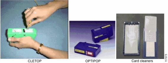
Dry Cleaning Technique: Cartridge and Pocket Style Cleaners

This section describes dry cleaning techniques with the use of cartridge and pocket style cleaners.

Tools

117073.gif

caution Caution: Read the reminders and warnings before you begin this process.

  1. Make sure that the lasers are turned off before you begin the inspection.

    warning Warning: Invisible laser radiation might be emitted from disconnected fibers or connectors. Do not stare into beams or view directly with optical instruments.

  2. Remove the protective endcap and store it in a small resealable container.

  3. Inspect the connector with a fiberscope. See the Connector Inspection Technique section.

  4. If the connector is dirty, clean with a cartridge or pocket cleaner.

    • For cartridge cleaners, press down and hold the thumb lever. The shutter slides back and exposes a new cleaning area, then go to step 5.

    • For pocket cleaners, peel back protective film for one cleaning surface, and then go to step 5.

    • For manual advance cleaners, pull on the cleaning material from the bottom of the device until a new strip appears in the cleaning window, and then go to step 5.

  5. Hold the fiber tip lightly against the cleaning area.

    • For single, non-APC fiber connectors, rotate the fiber once through a quarter turn, 90 degrees.

    • For APC connector endfaces, hold cleaning area at the same angle as the endface.

  6. Pull the fiber tip lightly down the exposed cleaning area in the direction of the arrow or from top to bottom.

    caution Caution: Do not scrub the fiber against the fabric or clean over the same surface more than once. This can potentially contaminate or damage your connector.

    • For pocket style cleaners, go to step 8.

    • For single fiber connectors with the type A CLETOP, repeat the cleaning process in the second clean slot (step 5 and step 6).

  7. Release the thumb lever to close the cleaning window, if you use cartridge type cleaners.

  8. Inspect the connector again with the fiberscope. Refer to the Connector Inspection Technique section.

  9. Repeat the inspection and cleaning processes, as necessary.

    caution Caution: Throw away any used cleaning material, either cards or material cartridges, after use.

Dry Clean Technique: Lint-Free Wipes

This section describes dry cleaning techniques that use lint-free wipes.

Tools

  • Lint-free wipes, preferably clean room quality

Figure 8

95147.gif

caution Caution: Read the reminders and warnings before you begin this process.

  1. Make sure that the lasers are turned off before you begin the inspection.

    warning Warning: Invisible laser radiation might be emitted from disconnected fibers or connectors. Do not stare into beams or view directly with optical instruments.

  2. Remove the protective endcap and store it in a small resealable container.

  3. Fold the wipe into a square about 4 to 8 layers thick, see Figure 8.

  4. Inspect the connector with a fiberscope. Refer to the Connector Inspection Technique section.

    If the connector is dirty, clean it with a lint-free wipe.

    caution Caution: Be careful not to contaminate the cleaning area of the wipe with your hands or on a surface during folding.

  5. Lightly wipe the ferrule tip in the central portion of the wipe with a figure 8 motion.

    caution Caution: Do not scrub the fiber against the wipe. If you do it, it can cause scratches and more contamination.

  6. Repeat the figure 8 wiping action on another clean section of the wipe.

  7. Properly dispose of the wipe.

  8. Inspect the connector again with the fiberscope.

  9. Repeat this process as necessary.

Dry Clean: Lint-Free Swabs

This section describes dry cleaning techniques that uses lint-free swabs.

Tools

  • Lint-free swabs, preferably clean room quality

Figure 9

117074.gif

caution Caution: Read the reminders and warnings before you begin this process.

  1. Make sure that the lasers are turned off before you begin the inspection.

    warning Warning: Invisible laser radiation might be emitted from disconnected fibers or connectors. Do not stare into beams or view directly with optical instruments.

  2. Remove the protective endcap and store it in a small resealable container.

  3. Inspect the connector with a fiberscope. Refer to the Connector Inspection Technique section.

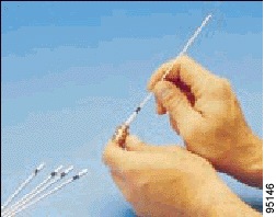
  4. If the connector is dirty, clean it with a lint-free swab.

    Figure 10

    95146.gif

  5. Lightly press and turn the swab to clean the ferrule face.

  6. Properly dispose of the swab. Never reuse a swab.

  7. Inspect the connector again with the fiberscope.

  8. Repeat this process as necessary.

Wet Cleaning Technique: Lint-Free Wipes

If a dry cleaning procedure does not remove the dirt from the fiber endface, then try the wet cleaning method.

caution Caution: Improper cleaning can cause damage to the equipment. The primary concern with the use of isopropyl alcohol is that it can be removed completely from the connector or adapter. Residual liquid alcohol acts as a transport mechanism for loose dirt on the endface. If the alcohol is allowed to evaporate slowly off the ferrule, it can leave residual material on the cladding and fiber core. This is extremely difficult to clean off without another wet cleaning and usually more difficult to remove than the original contaminant. Liquid alcohol can also remain in small crevices or cavities where it can re-emerge during fiber connection.

Tools

  • 99% isopropyl alcohol

  • Lint-free wipes

Figure 11

95147.gif

caution Caution: On female multifiber connectors, ensure that no alcohol gets into the guide pin holes. The alcohol might come out during mating and contaminate your connection.

caution Caution: Do not use wet cleaning on E-2000 or F-3000 connectors because the connector can trap the alcohol and re-contaminate the connector.

caution Caution: Read the reminders and warnings before you begin this process.

  1. Make sure that the lasers are turned off before you begin the inspection.

    warning Warning: Invisible laser radiation might be emitted from disconnected fibers or connectors. Do not stare into beams or view directly with optical instruments.

  2. Remove the protective endcap and store it in a small resealable container.

  3. Inspect the connector with a fiberscope. Refer to the Connector Inspection Technique section.

  4. Fold the wipe into a square, about 4 to 8 layers thick. See Figure 11.

  5. Moisten one section of the wipe with one drop of 99% alcohol. Be sure that a portion of the wipe remains dry.

  6. Lightly wipe the ferrule tip in the alcohol moistened portion of the wipe with a figure 8 motion. Immediately repeat the figure 8 wiping action on the dry section of wipe to remove any residual alcohol. (See Caution).

    caution Caution: Do not scrub the fiber against the wipe, doing so can cause scratches.

  7. Properly dispose of the wipe. Never reuse a wipe.

  8. Inspect the connector again with a fiberscope.

  9. Repeat the process as necessary.


Fiberopticcleanings.com stocks a variety of fiber optic cleaning supplies, from one click cleaners to NEOCLEAN-N optical connetor cleaner, from fiber optic cleaning wipes to fiber optic cleaning kit – everything you need for fiber optic cleaning jobs, BUY NOW and get FREE SHIPPING on most items!

400G first for submarine cable

Tata Communications, Huawei, and Huawei Marine have announced the successful completion of a 400G field trial on a subsea network over 6,000 km. The test results demonstrated an optical transmission of 400G signals, an industry-first for a submarine cable system of this length. 

Huawei and Huawei Marine say their technical solution ‘adopted the modulation format of dual carrier polarisation division multiplexing quadrature phase shift keying (DC-PDM-QPSK), an innovative ‘Faster-Than-Nyquist’ (FTN) compensation and recovery algorithm, proprietary clock recovery technology and soft decision forward error correction (SD-FEC) technology to address the problems of high-speed signal distortion and unstable clocks’. The use of such advanced technology underpins Huawei and Huawei Marine’s significant commitment to investing in research and development to meet the needs of their customers, the companies say.

Hon Kit Lam, vice president for international transmission and IP business at Tata Communications, said: ‘The 400G technology of Huawei & Huawei Marine demonstrates that our existing subsea network asset is capable of supporting future, next-generation transmission technology as shown in the 400G trial. Tata Communications constantly assesses new technology to expand our capabilities and to enhance our ability to support traffic growth demand from our customers.’

Jack Wang, president of Huawei Transmission Network Product Line, added: ‘Huawei has always taken a customer-centric approach to our research and development efforts. Our 400G technology will not only help operators manage larger levels of traffic faster, but also optimise operating and network maintenance costs. We are pleased to be working with leading international carriers like Tata Communications on this 400G technology trial.’