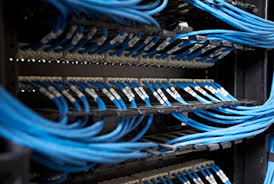
Market Growth Hinges on the Adoption of Next Generation Technologies


Demand for optical connectivity remains strong despite a declining capex of telecom network operators and lower than expected growth in infrastructure spending by cloud companies. Optics takes on a larger share of the connectivity as data rates go up. Increasing complexity of high-speed optics translates to higher product pricing, boosting revenues of component suppliers, while offering cost reductions to end users in terms of dollars per Gigabit of bandwidth.

The spending of the 15 leading network operators is set to drop in 2016. The operators’ guidance on their 4Q15 earnings calls means the Far East will spend less in 2016 and in the case of the Chinese operators, significantly less. The analytics forecast that capex will be down 7% to $178 billion dollars in 2016.
Read more

How Does a Fiber Identifier Work?

Optical Fiber Identifier

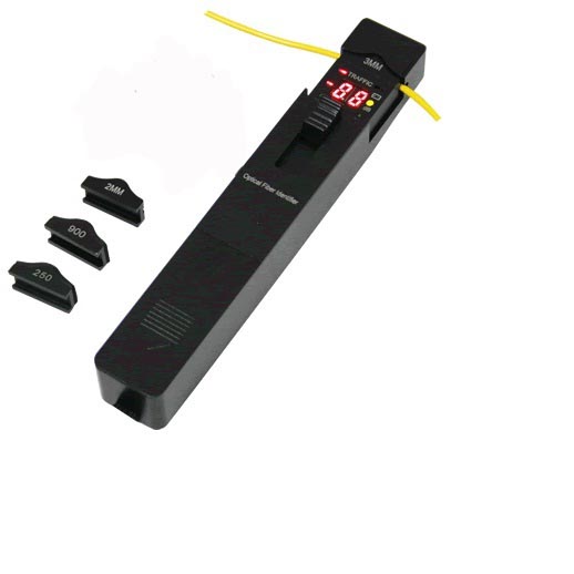
Simply put, the fiber identifier uses a super low insertion loss local detection method of macro-bending. This allows for detection of the optical signals during installation and maintenance without disconnecting the fiber or interrupting the traiffic signal.

This macro-bending method eliminates the need to open the optical fiber at the splice point reducing the probability of interrupting service to your customer.

SYOPTEK’S OFI-201 Optical Fiber Identifier is an essential installation and maintenance instrument. By inserting the fiber into its adapter to avoid the opening of the fiber at the splice point for identification and thus avoids the interruptiion of the service. In the presence of traffic, the intermittently audible tone is activated. This optical fiber identifier also allows relative core power display and identification of the 270 Hz, 1k Hz, and 2k Hz frequencies. When they are used to detect the frequency, the continuously audible tone is activated. There are four adapter heads available: Φ0.25, Φ0.9, Φ2.0, Φ3.0

Is OTDR testing necessary for premise cabling?

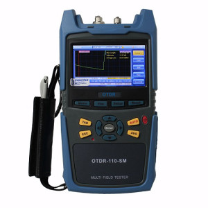
OTDRWhile there has been some “buzz” about Optical Time Domain Reflectometer(OTDR)testing for premises cabling since the publication of TSB-140, Additional Guidelines for Field-Testing Length, Loss and Polarity of Optical Fiber Cabling Systems, many agree that the test is usually not necessary for the relatively short links found in a customer-owned network, and may merely add unnecessary expense and complexity.

When testing an optical premises network, the key measurement criterion is insertion loss, or attenuation. This is effectively measured by using a power meter and light source. If the attenuation is within the limits of the allotted power budget, the system will work. OTDRs measure Raleigh backscatter, not absolute loss.

Supporters of OTDR testing in the premise environment believe that testing with an OTDR can help identify microbends that could potentially cause a problem; as well as help document the system for future verification. However, visual inspection is usually the best way to locate breaks or bends. While there may be some minor advantages in performing OTDR testing on premise cabling, the added cost usually outweighs the benefits.

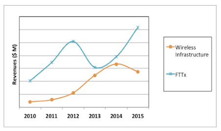
The global market for FTTx gptical components and modules will set for a second wave of growth in 2016-2020.

FWDM Chassis
Network operators in Hong Kong, Japan and Korea have connected close to 100% of their domestic residents with fiber and are starting to offer 1G and even 10G speeds. For a selected few customers, docking their yachts in Hong Kong’s harbors, 1 Gbps fiber to the yacht (FTTy) connections are now available. However today, 1G connectivity in itself is not a luxury. According to Amano-san of NTT, 1 Gbps connectivity today costs customers in Japan less than 10Mbps service did back in 2001. That is a factor of 100 improvement in speed and cost per Gbps over the last 15 years!

China leads the world in the total number of FTTx subscribers, which is expected to exceed 100 million by the end of 2015. The Chinese government’s latest plan calls for doubling the connectivity speed by the end of 2015, while reducing the end user’s cost by 40%. India and Indonesia are just starting to deploy FTTx, as their governments have approved very ambitious plans to bring fiber connectivity to even the smallest and most remote villages. “FTTz” as mentioned in the title, is not a real term, but it symbolizes extending fiber to every last resident of the region.
Read more

Is Silicon Photonics a disruptive technology ?

123
Many in the industry have predicted that Silicon Photonics (SiP) will enable inexpensive, mass produced optical connectivity, radically changing the optical components and modules industry. Our analysis suggests this will not happen in the next 5 years, but sales of SiP-based optical products may reach $1 billion by 2020, accounting for about 10% of the market.

As often happens with new technologies, product sales are starting to ramp up just as industry expectations start to fade, as illustrated in Figure (Typical trend for cross-correlation between industry expectation for new technologies and product sales) above.

It seems clear that several SiP suppliers demonstrated that this technology works. However, it is up to the manufacturing engineers and business managers of these suppliers to show that SiP products can be made in high volume at a competitive cost and generate profits to fund development of next generation products.
Read more

What factors affect optical fiber splicing loss?

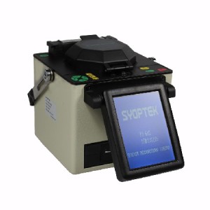
FS-60S Fusion SplicerThere are two types of factors that fiber splice loss depends on: intrinsic factors and extrinsic factors.

1、intrinsic factors
Mode Field Diameter Mismatch

Intrinsic factors are parameters that you can not control. These factors are determined when the fiber is manufactured and Mode Field Diameter (MFD) is the most critical one.

Differences in the mode field diameter between single mode fibers lead to a signal loss. More splice loss can be observed for higher difference in MFD values.
Read more

How to choose a best fiber optic power meter.

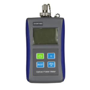
optical power meterFiber optic power meter measures how much light is coming out of a fiber optic cable; it can be used to determine the amount of light being generated by an optical source, or the amount of light being coupled into an optical receiver.

Optical power is usually measured in dBm, or decibels referenced to 1mW. These devices measure the average optical power, no the peak power, so they are sensitive to the duty cycle of the data transmitted. Their wavelength and power range have to be appropriately matched to the system being measured.

Most power meters used to best communication networks are designed to work at 850nm, 1300nm, and 1550nm wavelength ranges and in the power range of –15dBm to –35dBm for multimode links, or 0-40 dBm for single mode links.
Read more

Best Practices for Data Center Fiber-Optic Cabling Systems

images2Fiber-optic cabling is an ideal medium for data center networks, because of fiber’s ability to support high transmission speeds and long-distance connections. Many factors come into play when planning, deploying and administering a data center fiber-optic cabling system.
The following are some suggestions for efficient cabling and network management.

Presentation 1: Fiber-optic Port Replication—How and Why
Large volumes of connections in a densely packed environment are a hallmark of fiber-optic networks. In these connectivity environments, managing the large volume of fiber-optic cables can be a constant challenge. One means of easing and simplifying this management is to implement passive port replication. This presentation describes what port replication is, how it can be accomplished, and why it eases the cable-management burden for a data center administrator.

Presentation 2: Testing and Assuring Fiber Connections
Once a fiber-optic cabling infrastructure is installed to support data center networking, that infrastructure must be tested to ensure it performs at the expected performance level and supports the intended applications. This presentation discusses several critical aspects of fiber-optic testing, including proper reference setting, the role of encircled flux (EF) and its implications on test tools/procedures, as well as the ability to test different connector-endface types with a single test unit.

Presentation 3: Fiber Splicing in the Data Center
While preterminated systems have gained popularity for some data center settings and circumstances, many data center fiber-optic cabling systems can benefit from fusion-spliced connections. This presentation explains the circumstances under which splicing fiber represents an efficient and effective connectivity method. It describes the splicing technologies and techniques that can be put to effective use in data centers.
Why do we need to cleave optical fibers?

image5
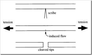
Optical fiber needs to be cleaved for fusion splicing. Optical fiber fusion splicing nearly always requires that the fiber tips exhibit a smooth end face that is perpendicular to the fiber axis.

This sufficiently perpendicular and planar fiber end face can be achieved via the fiber cleaving process. In this cleaving process, the brittle glass fiber is fractured in a controlled manner.

Polishing a fiber tip can result in even higher quality fiber end faces, but polishing requires more expensive equipment and more processing time, so it is very rarely employed for fusion splicing.

FS-C20 Fiber CleaverA fiber optic cleaver is a piece of tool or equipment to make an almost perfect fiber end face cut. Just like using a diamond scribe tool when cutting glass, a fiber cleaver’s cutting wheel (blade) makes a very tiny cut on the fiber first, then the fiber is pressed against the little cut to force it to break at 90° angle and expose a mirror like fiber end face.

The SYOPTEK FS-C20 Fiber Cleaver is designed to precisely cleave all 125um multimode or singlemode optical fibers. The high precise adjustable blade can perform up to 60,000 cleaves with a typical cleave angle of 90 degree.


How to Use FIP-800-D Fiber Optic Cleaning, Inspection Kit.

FIP-800-D Fiber Optic Cleaning, Inspection Kit provide a complete selection of fiber optic cleaning products for field cleaning, inspection of connector endfaces in a hard-side carrying case.

It contains everything needed to eliminate the #1 cause of fiber optic network failure: contamination.

FIP-800-D Fiber Optic Cleaning, Inspection Kit includes FIP-800 fiber optic inspection probe, one click cleaner for SC, ST, FC connectors, one click cleaner for LC, MU connectors, NEOCLEAN-N Optical Connector Cleaner, replacement reel for NEOCLEAN-N fiber cleaner in a hard-side carrying case.