How To Make A Perfect Fusion Splice?

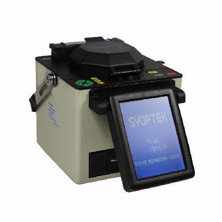
fusion splicer

Fusion splice process is to literally weld two prepared fiber ends together, thereby creating a permanent joint with the minimum possible insertion loss. The fusion splice process is illustrated as follows.

Fusion Splice

So what factors in the fusion splice process determine the insertion loss achieved? The loss mechanism in fusion splice joint may be summarized as follows:

  • Core misalignment. Although normally aligned using the cladding diameter as the reference surface, it is generally believed that the complex surface tension and viscosity structures within the core and the cladding do tend to minimize the actual core misalignment.
  • Core diameter. The allowable diameter tolerances creates the possibility of attenuation within the joint.
    However, where differences between core diameters are large the welding of core to cladding inevitably takes place, which can either exaggerate or reduce the resultant losses. As a logical extension to this it should be obvious that optical fibers having different geometries are difficult if not impossible to joint using the fusion splice method.
  • Numerical aperture. The above comments regarding core diameter apply also to numerical aperture mismatches.

In addition to these losses, which are almost unavoidable, the level of skill involved in the process demands few abilities other than those necessary to prepare the fiber ends by cleaving. Nevertheless, poor levels of cleanliness and unacceptable cleaving of the ends will incur additional losses due to the inclusion of air bubbles or cracks. Incorrect equipment settings will also influence losses achieved and may result in incomplete fusion.

Fusion splicing is capable of producing the lowest loss joints within any optical fiber system, but their permanence limits their application. The need for demountable connections necessary to facilitate patching, repair and connection to terminal equipment forces the use of jointing techniques which use mechanical splices.

Ideal Networks offers online quote builder for cable test hardware packages

OTDRIdeal Networks recently unveiled an online Quote Builder that the company says “enables network cable installers to easily select a cable certifier package that meets their specific job requirements, helping to drive down purchase costs.”

Tim Widdershoven, global marketing manager for Ideal Networks, describes the Quote Builder as “an easy-to-use visual guide that enables cable installers to make an informed buying decision” while building a tailored fiber optic tester solution. Widdershoven continued, “Previously, cable certifiers have only been available in bundles, which may include extra components or functionality that a customer will simply never use. Using our new Quote Builder function online, customers can pick-and-mix from various options to find a certifier that meets their specific requirements and budget in six simple steps.”

Users of the Quote Builder begin by choosing either a 500-MHz Category 6A or 1000-MHz Category 7A certifier, then adding adapters. Permanent link adapters can be used for testing cabling from the outlet to the patch panel, or channel adapters can be used to certify the entire link—including patch cords. Next, users select any fiber modules required, to add Tier 1 fiber-optic cable certification. Following that, accessories are added, such as calibration cables, coaxial adapters, or an industrial Ethernet kit if required. Finally, users select a 1-, 2-, or 3-year CarePlan. Once the user enters some basic contact information, the user receives a quote.

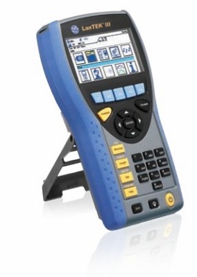
Ideal Networks further pointed out that one piece of fiber opitc test equipment users can specify via the Quote Builder is its LanTek III Cable Certifier (pictured). Introduced in December, the LanTek III is available in 500-MHz (Category 6A) and 1000-MHz (Category 7A) models. “For fiber cabling, the new FiberTek III modules can be added to the LanTek III-500 or LanTek III-1000 models to provide Tier 1 certification, eliminating the need for additional fiber testers,” Ideal Networks said.

The Most Convenient Way to Clean Fiber Optic Adapter

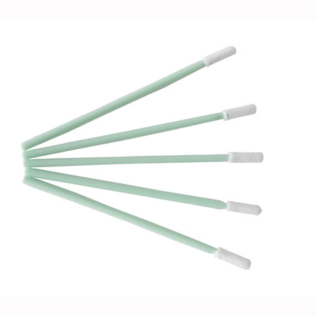
CS-001 2.5mm Fiber Optic Foam Swabs

Fiber optic adapters (mating sleeves) are used to mechanically connect two fiber connectors. A fiber adapter consists of two main parts: the connector alignment sleeve and the adapter housing.Connector alignment sleeve is usually a split “C” and is made from a hard, low-wear material such as Zirconia (a type of ceramic ) and phosphor bronze.

The alignment sleeve is the most critical part since it provides the alignment of two connector ferrules.

In the late 1990s, The Technologies studied the reliability of fiber optic enclosures in outside plant environment (field enclosures). They assembled a report on the benefits of fiber connection cleaning in those fiber optic OSP enclosures. The statistics showed a significant improvement after connector and adapter cleaning.

The best practice is to clean an adapter or connector thoroughly before mating whenever your insertion loss suddenly increases.

The most convenient way to clean it is with the fiber optic cleaning swabs.

Transceivers for mobile fronthaul to top $1 billion by 2020

Almost everyone supplying transceivers for fronthaul applications now knows that 2014 was a fantastic year, and that 2015 is a little soft in comparison. In spite of this, the investigators are predicting that the fronthaul optics market will resume growth in 2016, and reach over $1 billion in sales by the year 2020.

How can they be so sure?

First, because the market softness in 2015 is temporary. China Mobile deployed an astonishing 733,000 LTE basestations in 2014, but will only install 100,000 or so this year, partly due to a politically driven reorganization. China Telecom and China Unicom have ramped up LTE deployment now, but it’s not enough to offset the decline in China Mobile’s consumption. However, the LTE tide is still rising around the world and we believe initial deployments and capacity upgrades will increase demand for fronthaul transceivers steadily from now through 2020.

Second, the analysis of recent data on mobile traffic growth.

1-1Figure 1 – Network traffic growth rates

Figure 1 shows the Internet traffic growth overall, global mobile data traffic, and mobile traffic growth in China. The global mobile traffic is a composite of Cisco VNI and Ericsson Mobility Report data, while the data for China comes from the Chinese Ministry of Industry and Information Technology.

The traffic growth data shows just how dramatic the shift to mobile networks has been in the smartphone era, with mobile traffic growing at rates 20-25 points higher than overall Internet traffic. And the data from China is even more dramatic, showing a jump in traffic growth in 2015, following deployment of LTE by China Mobile the year before. Over the next five years the growth estimates range from 60% to 40% per year, meaning that mobile networks will have to carry seven times more traffic in 2020 than in 2015. And estimates of mobile data traffic growth have been increasing: Ericsson raised its estimated CAGR from 45% to 55% between its 2014 and 2015 Mobility Reports.

The investigator also use the traffic data to do a ‘sanity check’ on their forecast.
First they calculate the total cumulative bandwidth implied by our fronthaul forecast, and then they calculate the associated growth rates, and compare them to the traffic growth rates, as shown in Figure 2. You can see that our forecast growth rates for fronthaul bandwidth are lower than the traffic growth rates, and this is despite the fact that they are predicting significant use of 25G modules for fronthaul starting in 2018. So if anything, we feel our forecast is conservative.

1-2Figure 2 – Fronthaul bandwidth vs. mobile traffic growth rates

SYOPTEK has highly efficient production and international quality control system, hold strong R&D capability and first-class manufacturing process/test equipments, our passive optical components product line includes WDM, CWDM, DWDM, FWDM, optical isolator, optical circulator, in-line VOA, polarization maintaining optical products and connectors.

How to Keep the Fiber Optic Connectors Clean?

One Click Cleaner|Fiber Optic Cleaner

As we know, single mode fibers have cores that are only 8~9um in diameter. As a point of reference, a typical human air is 50~75um in diameter, approximately 6-9 times larger.SO it is hard to conceive of the size of a fiber optic connector core.

Dust particles can be 20um or larger in diameter. Dust particles smaller than 1um can be suspended almost indefinitely in the air. A 1um dust particle landing on the core of single mode fiber can cause up to 1dB of loss. Larger dust particles, 9um or larger, can completely block the core of a single mode fiber.

Such that fiber optic connectors have to be cleaned each time they are mated. It is essential that fiber optics users develop the necessary discipline such as one click cleaner or fiber optic cleaner to always clean the connectors before they are mated.

Unprotected connector ends are most often damaged by impact, such as hitting the floor. Most connector manufacturers provide some sort of protection boot. The best protectors cover the entire connector end, but they are generally simple closed-end plastic tubes that fit snugly over the ferrule only. So cover a fiber optic connector when it is not in use is the other important thing should be  keep in mind .

These boot will protect the connector’s polished ferrule end from impact damage that might crack or chip the polished surface. Many of the tight fitting plastic tubes contain jelly-like contamination (most likely mold release) that adheres to the sides of the ferrule. A blast of cleaning air or a quick dunk in a alcohol will not remove this residue. This jelly-like residue can combine with common dirt to form a sticky mess that causes the connector ferrule to stick in the mating adapter. Often, the stuck ferrule will break off as one attempts to remove it.
The most inporment thing is that always thoroughly clean the connector with fiber optic cleaner before mating, even if it was cleaned previously before the protection boot was installed.

Why fiber optic connector cleaning is so important?

fiber optic cleaner
Reliable optical networks require clean connectors. Any time one connector is mated to another, both connectors should be properly cleaned and inspected.

Dirty connectors are the biggest cause of increased back-reflection and insertion loss in connectors, including angled polish connectors.

a. Increased back-reflection and insertion loss in connectors

A dirty ultra polish connector with a normal return loss of >55dB can easily have >45dB reflectance if it is not cleaned properly. Similar comparisons can be made with angled polish connectors. This can greatly affect system performance, especially in CATV applications where carrier-to-noise ratios (CNR) are directly related to signal quality.

b. Jeopardize the long-term reliability of the network

Dirty connectors can also jeopardize the long-term reliability of the network, because dirt and debris can be embedded into the endface of the connector, causing permanent, performance-affecting damage.

In order to ensure that both connectors are properly cleaned, the termination panel must allow them both to be easily accessed. This easy access has to be for both the patch cord connector and the equipment or OSP connector on the back side of the termination panel. Accessing these connectors should not cause any significant loss in adjacent fibers.

A system that allows uncomplicated access to these connectors has much lower operating costs and improved reliability. Without easy access to connectors, technicians will take more time to perform their work, delaying implementation of new services or redeployment of existing services.

The technicians  must be choose the fiber optic cleaner  to clean up the connectors to make the fiber optic works well.

Strong finish expected for optical components in 2015

1

Four times a year, the reseach team collects company financials and operating metrics from across the optical communications value chain, and they receive proprietary shipment data from more than 20 optical components vendors. They review the data, compare it to our existing forecasts, and tell clients what is happening in the market, in the form of a Quarterly Market Update.

The just-published September 2015 update reflects their analysis of financials and vendor shipment data through the first half of 2015, and industry news through Q3 2015. This graphic from the report summarizes the growth in service provider capex, and equipment and component vendor revenues, for 2Q 2015 compared to 2Q 2014.

It’s clear that telecom service provider capex fell off in the first half of 2015 compared to 2014, due to completion or tapering down of some large deployment projects around the globe, including China Mobile’s LTE deployment, Vodafone’s Project Spring, and Sprint’s Network Vision. Mega-datacenter operators on the other hand increased spending by 7%, which although positive, is smaller than the double-digit growth rates we are used to seeing for this group.

Equipment maker revenues grew a scant 2% and 4% in the datacom and telecom segments, respectively. ‘White box’ makers continue to make inroads in the datacenter equipment segment, while on the telecom side, Huawei’s and ZTE’s market shares gallop upward, and those of other incumbents languish. Pricing pressure continues to weigh heavily on revenue growth. Keen interest in Software Defined Networking and Network Function Virtualization may also be a factor in dampening equipment demand, as service providers take a breather to rethink their network plans.

2

2Q15 sales growth among optical component companies was a little better than at the equipment level, with datacom up 10% and telecom up 7%. One of the main reasons for this is the growing adoption of 100Gbps components, which carry a higher price tag than slower speed devices.

The second chart (below) shows 2Q 2015 sales growth for the main product categories that we forecast. Ethernet and WDM are the two largest segments in terms of revenues, and both grew at a respectable/healthy rate. Optical interconnects continued to show rapid growth but are still a very small segment, totaling a little over $50 million in sales in 2Q 2015. FTTx also experienced high growth, driven by an acceleration of China’s broadband plans. The wireless segment on the other hand was down considerably, but that was to be expected given the extraordinary amount of LTE gear deployed by China Mobile in 2014.

They projected total optical transceiver market growth of 25% in 2015. Subsequently, some public optical components companies gave rather soft guidance for the balance of the year in their 2Q 2015 earnings calls, and political developments in China have called capex spending there into question. Based on our analysis of the most recent data and news, they have also decided to soften their outlook for optical components sales in 2015, but only to the extent of reducing our forecast growth rate from 25% to 15%. Even at this lower growth rate, full-year 2015 industry revenues should set a new record high, above $4 billion. One of the reasons They did not reduce the outlook more is that we are seeing private companies growing faster than the industry average and winning market share from the larger public vendors.

How to choose a best fiber optic inspection microscope?

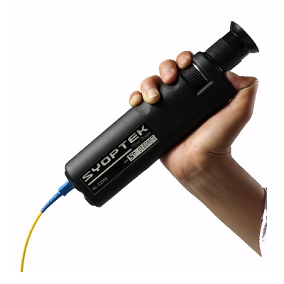
Fiber Optic Inpection Microscope

There are at least a dozen of different fiber optic inspection microscope on the market. So how do you choose one that is best for your application and budget? Here are some suggestions.

Consider your fiber inspection scope application environment

  • Production environment
  • Fiber optic cable installer contractors
  • Network manager

Consider your fiber optic cable and connector type

  • Single mode. Choose a fiber inspection scope with at least 200X magnification. Or even 400X if you are in a production environment.
  • Multimode, 100X maybe OK for field fiber optic cable termination. But best choice will still be a hand held 200X level scope.

SYOPTEK offers a range of fiber optic inspection microscope. Even better we have a extensive list of selection criteria published together with the products list.

View  SYOPTEK’s Fiber Optic Inspection Microscope product section to see the list of choices.

Electronics Technicians Association introduces new cabling certification

The Electronics Technicians Association—ETA International—recently announced it has established the Termination and Testing Technician certification for cabling professionals. The association’s president Teresa Maher said, “ETA International intends to lead the industry in providing certification for Termination and Testing Technicians to insure they have the knowledge and hands-on skills required to provide a system that will pass appropriate tests and is properly terminated.” The association added, “Since 80 percent of installation failures are related to poor connectorization techniques, ETA requires a hands-on skills test in addition to the knowledge portion of the test to validate the technician has acquired proper testing and termination techniques.”

The ETA said that as manufacturers develop Internet Protocol (IP) products to meet customer demand for faster speeds and increased bandwidth, skilled technicians are needed to test and terminate fiber-optic, copper and coaxial cabling. Termination and Testing Technicians (TTTs) “terminate, connect, test and troubleshoot IP-enabled voice/data/video cable and devices to each other using connectors, tools and techniques specific to fiber-optic, copper pairs, and coaxial cabling,” the association noted. “One of the primary principles of the network cabling standards is that if a cable is properly terminated and tests satisfactorily, that cable can be used to connect any proper device from any manufacturer. There are hundreds of vendors making thousands of different IP network devices, any and all of which can be readily connected to a network if the cable to be used is properly terminated and tested.”

Maher added, “This certification emphasizes ETA’s dedication to being vendor-neutral and applying industry standards for terminations, tests and cable performance across the board to all manufacturers’ products.”

The competency requirements for the TTT certification emphasize the use of cabling systems in IP security applications. Of the 13 general competency categories, the following 6 directly relate to IP security.

•Physical Security Systems Network Cabling Fundamentals
•General Fiber Optics Cabling for Physical Security Systems
•CCTV Fiber Transceiver Specifications
•General Copper Network Cabling for Physical Security Systems
•Using Power over Ethernet with Physical Security Devices
•Ethernet Coax Cables for Physical Security Systems/Devices

The other competency categories are:

•Technician Fiber Optic Safety
Fiber Optic Connectors
•Fiber Optics Hands-On Skills Exercises
•Unshielded Twisted Pair Cabling
•UTP Connectors
•Copper Testers and Troubleshooting
•UTP Cat 5e Hands-On Skills Exercises

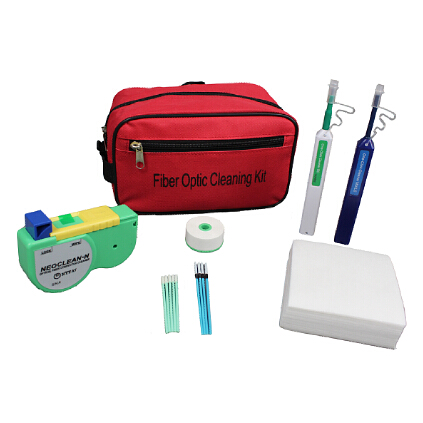
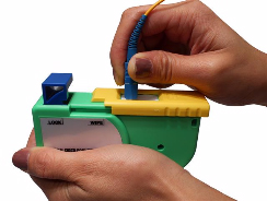
Fiberopticcleanings.com stocks a variety of fiber optic cleaning supplies, from one click cleaner to NEOCLEAN-N optical connetor cleaner, from fiber optic cleaning wipes to fiber optic cleaning kit – everything you need for fiber optic cleaning jobs, BUY NOW and get FREE SHIPPING on most items!

SYOPTEK designs and manufactures fiber optic test equipments


SYOPTEK designs and manufactures fiber optic test equipment for optical fiber cabling installing, maintenance, and verification; provides you quality, reliable fiber optic test equipment at a affordable price.

SYOPTEK fiber optic test equipment line includes Fiber Optic Inspection Probe, Fiber Optic Inspection Microscope, Optical Light Source, Optical Power Meter, Optical Fiber Identifier, Fusion Splicer, and Visual Fault Locator.